Chris's camera pages
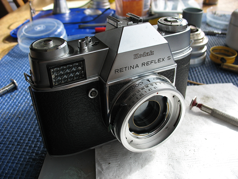
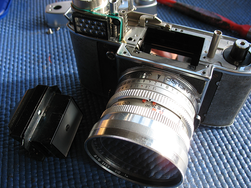
Retina Reflex S strip-down continued: Final assembly.
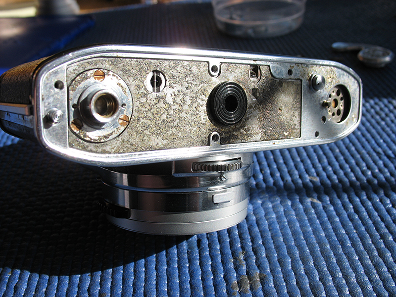
With the shutter done, the last task is to finish the final assembly. Remove the film advance lever, refit the chrome base-plate trim if you haven't already done so, and tighten the screws.
Refit the film advance lever.
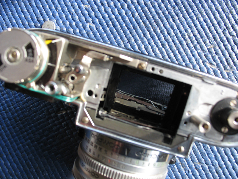
Assuming that the prism does not require dismantling and cleaning, it can now be refitted to the body. Note that there are more than a few fish-hooks involved in cleaning the finder assembly. Suffice it to say that there is no sense in taking it apart just because there are one or two specks visible. I'll cover this in more detail at another time. I'll leave a link here to the viewfinder assembly cleaning when I do.
The two screws that hold the top chrome trim to the body should now be fitted.
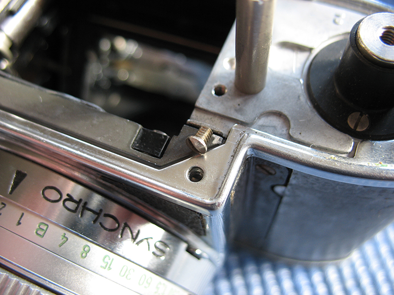
Crank the advance lever half-way to move the shutter-cocking rack out of the way of the prism. Note that you need to hold down the lock assembly, that pointy rod by the meter, to free-up the film advance while the top cover is off the camera.
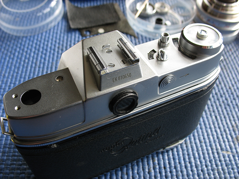
Push the finder assembly into place and fit the three screws. The two screws with the wider heads fit either side of the prism.
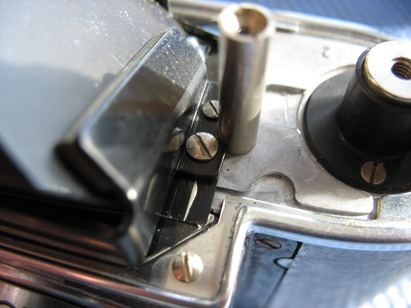
The screw with the narrower head fits at the back of the prism.
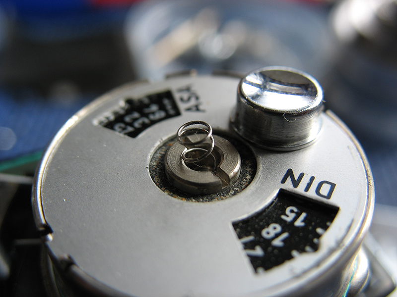
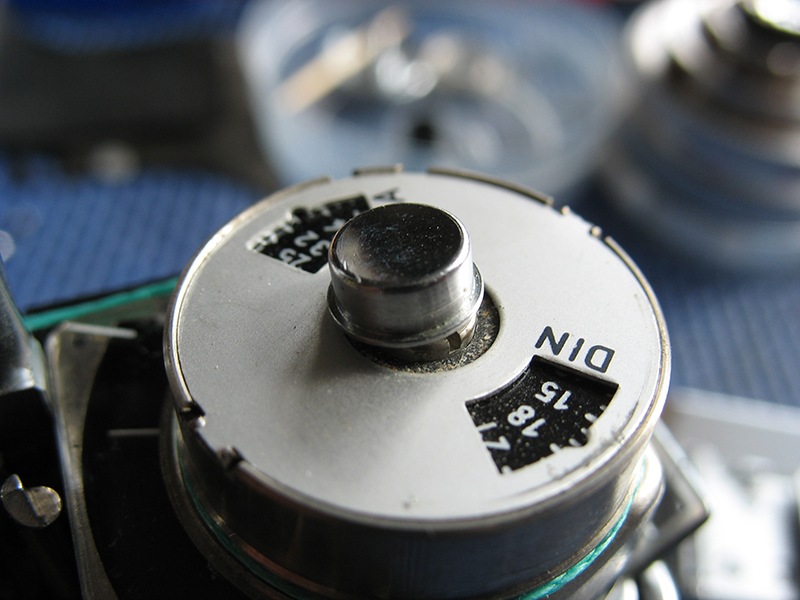
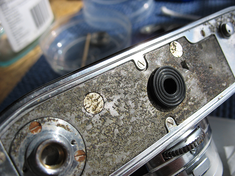
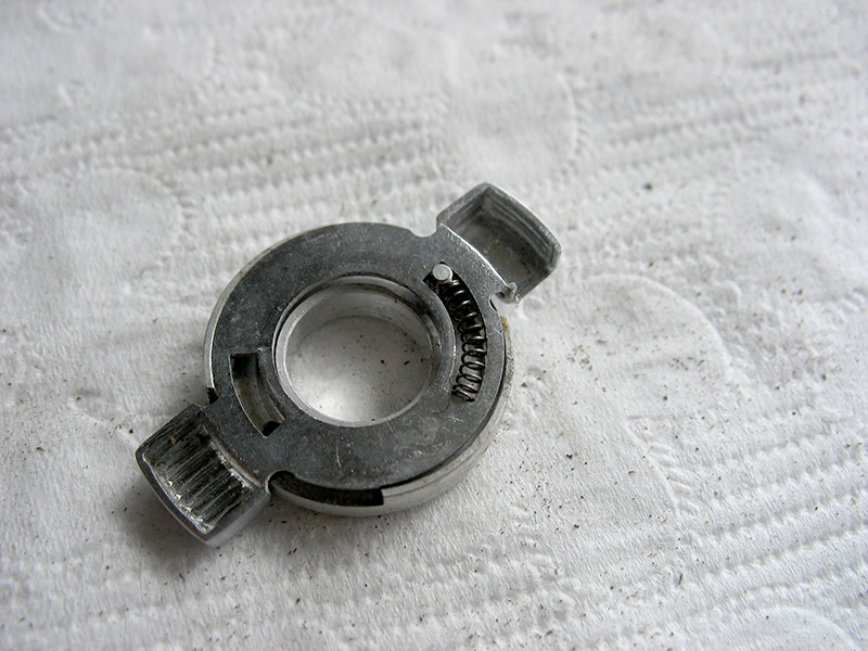
The exposure meter setting button and its return spring now need to be put in place. Note that I have assumed here just to speed up the process that the meter has been correctly reinstalled earlier and that the adjustment is also accurate. I will post instructions on how to adjust the meter for accuracy at a later date.
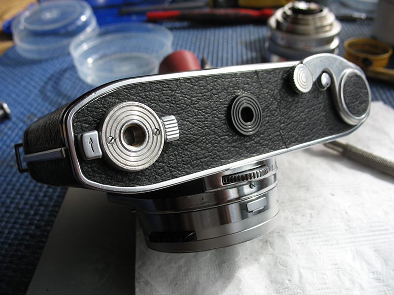
Clean the top cover, the viewfinder window, the meter window etc. and fit back on the camera.
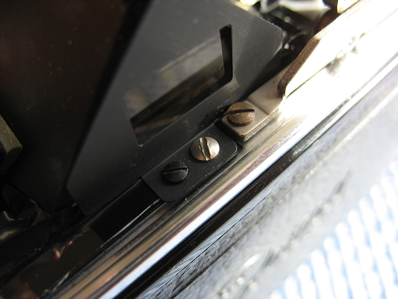
One large chrome-plated screw at the end of the top cover.
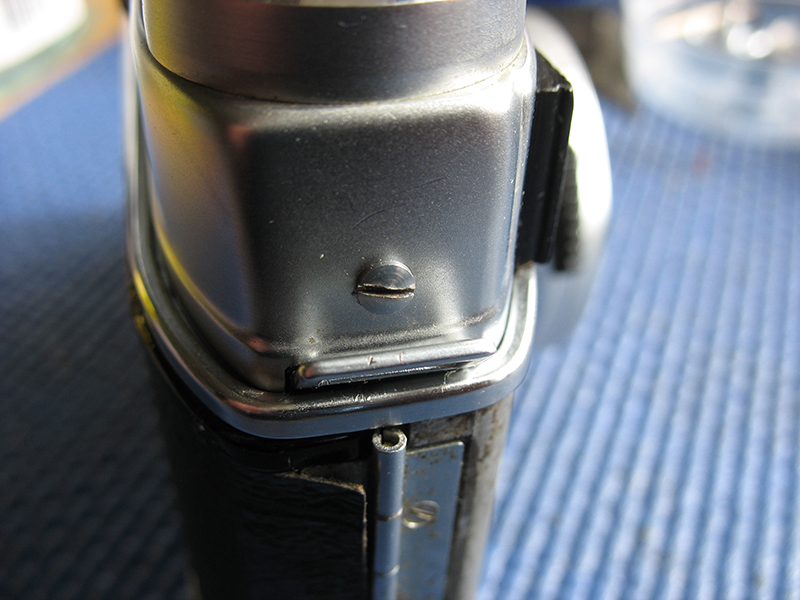
Two smaller chrome-plated countersunk screws and the chrome-plated pin-head screw at the other end of the top cover.
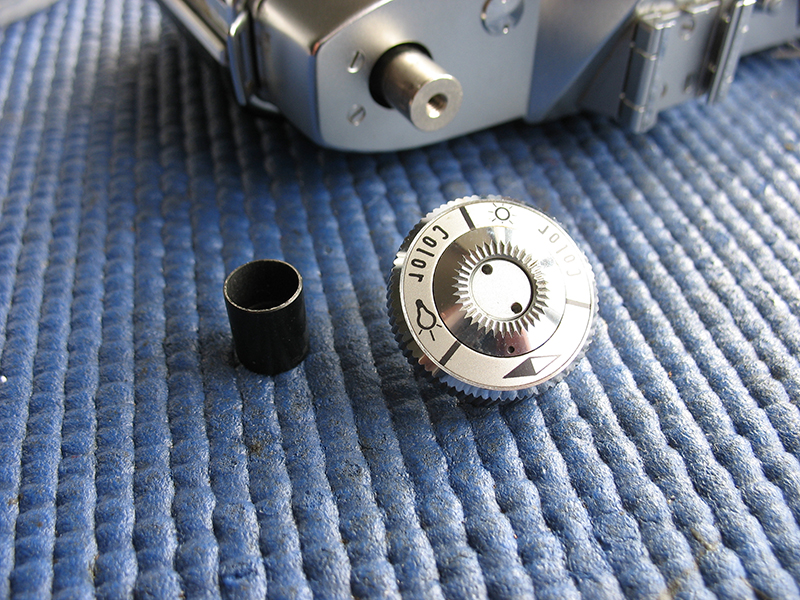
Note that the rewind knob also has a black spacer fitted below the knob.
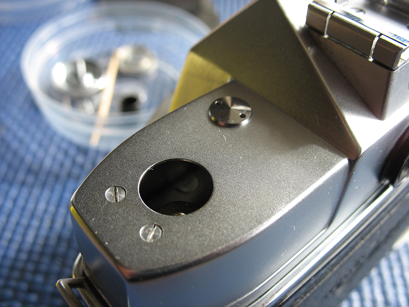
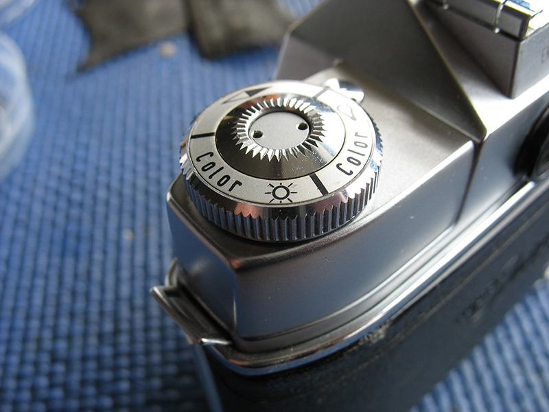
Screw the knob into place. I put a screwdriver through the rewind fork to stop the shaft turning and screw the knob on using my fingers.
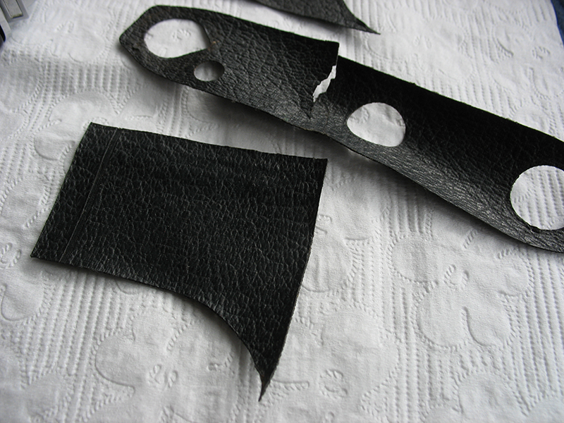
Next the leatherettes need to glued back into place on the body.
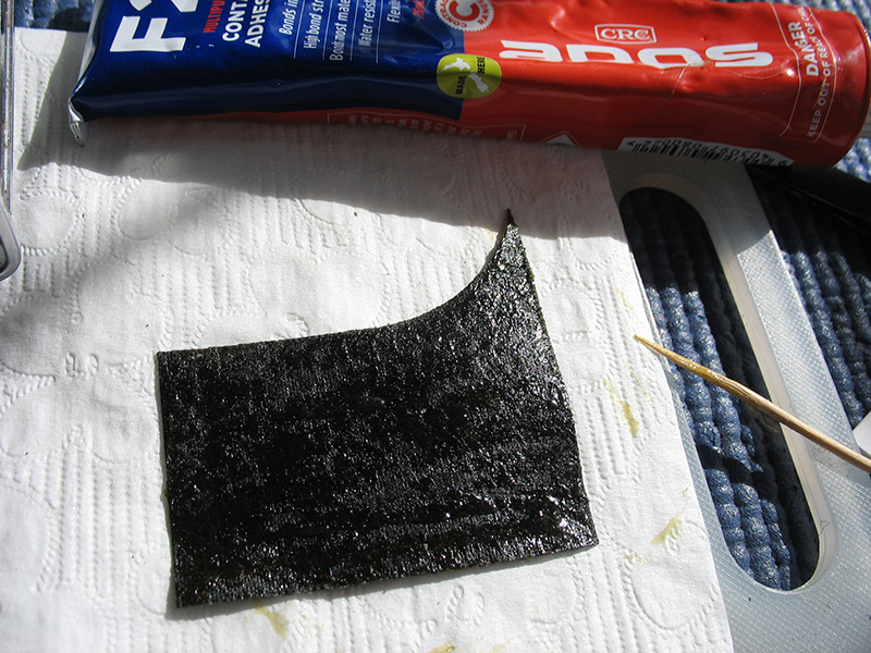
I have applied adhesive to one leatherette, spreading it evenly with a toothpick. Try to avoid getting any adhesive on the face of the leatherette. The leatherette is fitted itno place while the adhesive is still wet.
There should be two small round aluminium disks to cover the cut-outs in the baseplate.
This leatherette was already cut before I took the camera apart. Once stuck firmly in place the cut can be disguised with black wax.
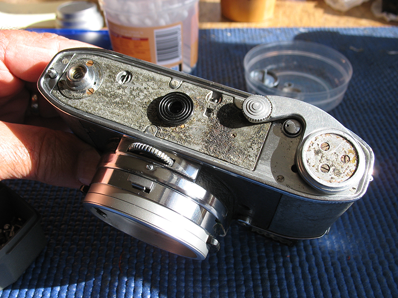
Assemble the back release cover assembly and its spring together with one screw like this.
Carefully move the back release cover assembly into place, tighten the screw, and fit remaining screw. Fit the advance lever and its leatherette patch.
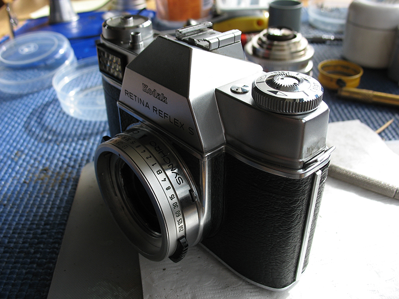
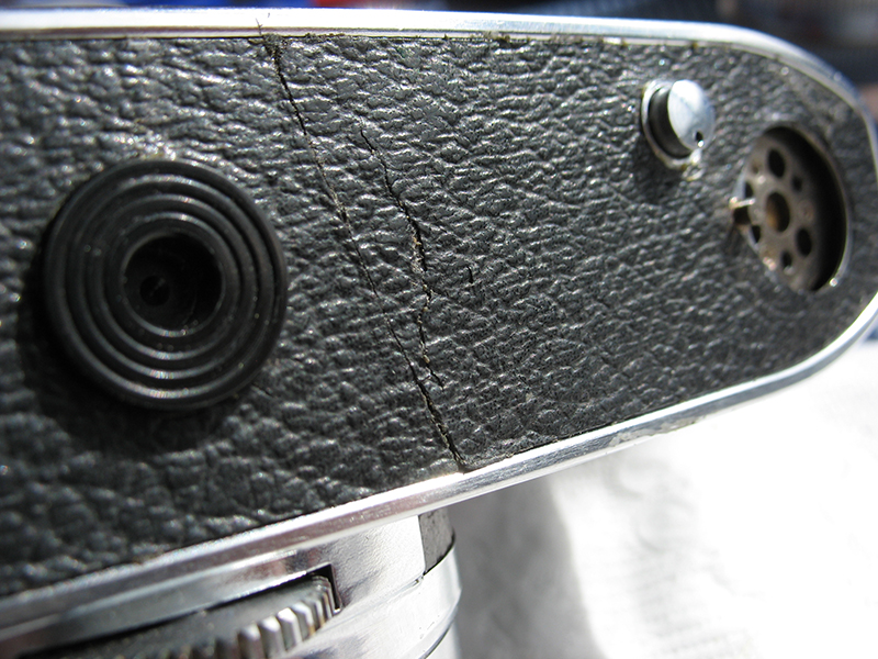
Back together again and ready to use. What didn't I cover here? A number of things, the cleaning of the finder assembly, the adjustment of the mirror to bring point of focus in the viewfinder into line with the image at the film plane, the meter adjustment, and what to do if the various rods and levers that operate the mirror and capping plate are bent or sticking....That'll have to wait for another time.