Chris's camera pages
How to strip-down and service the Synchro-Compur shutter on a Kodak Retina Ia or IIa camera
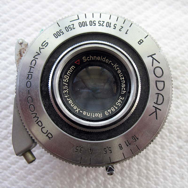
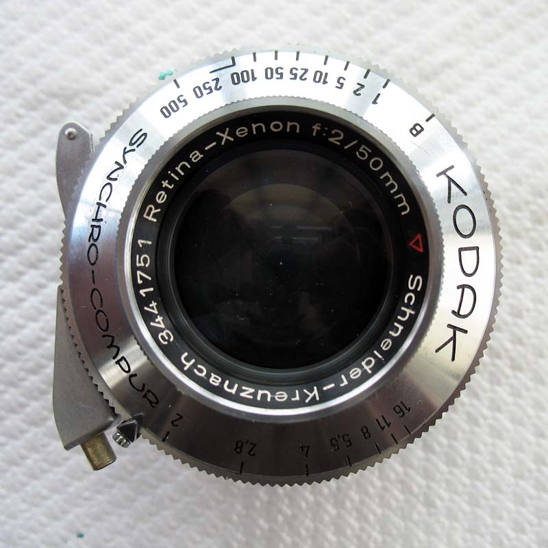
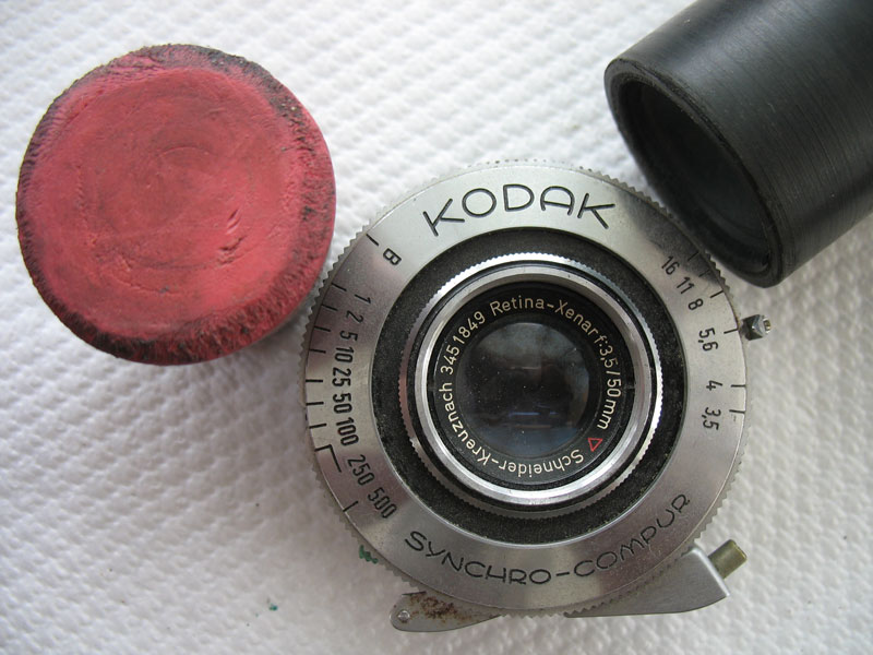
I'll assume you already have the shutter removed from the camera.You can find instructions for removing the shutter here.Access to the shutter is always from the front first because there are components that must be removed from the mechanism plate before the mechanism plate can be separated from the shutter case.Failure to dismantle the shutter in this order will likely lead to damage.The front lens should first be unscrewed.Ideally, just use your fingers. This should be fine for a Retina IIa, and perhaps for a Retina Ia, but if the lens is too hard to shift, use a friction tool instead. Do not use pliers or any other similar tool.
Lift off the front lens and the spacer/washer beneath it.
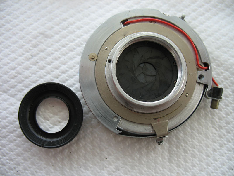
Unscrew the rear lens.This should come loose with your fingers on a Retina IIa, but on a Retina Ia you might need to use a friction tool.
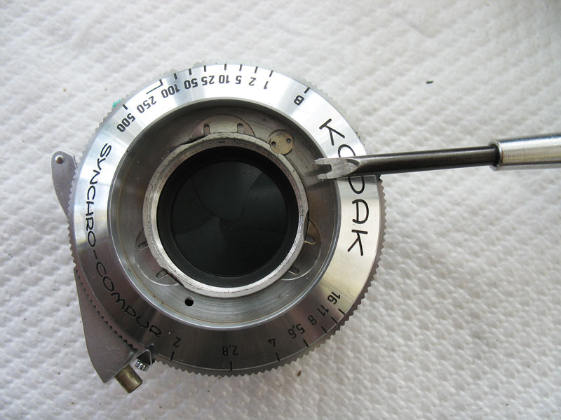
Rotate the pin-head lock screw at the front of the shutter.This task is much easier if you use a screwdriver modified for the task, but the tips of a pair of stiff tweezers may work well enough.
The screw has been rotated here to allow the front of the shutter to be rotated.Turn the front plate of the shutter anti-clockwise to align the tabs with the notches in the centre of the shutter.
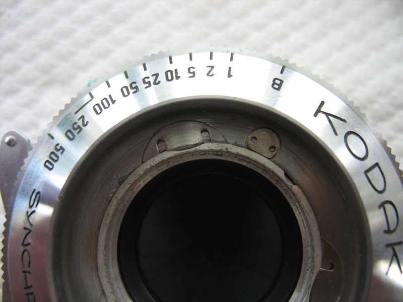
Lift off the front plate, but leave the speed cam in place.

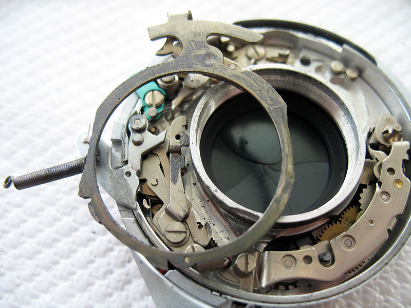
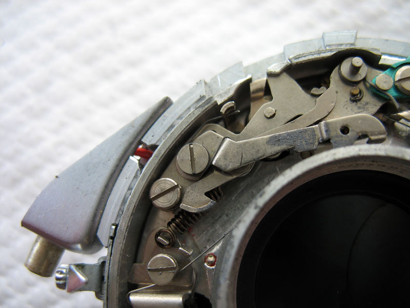
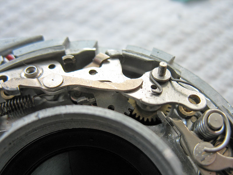
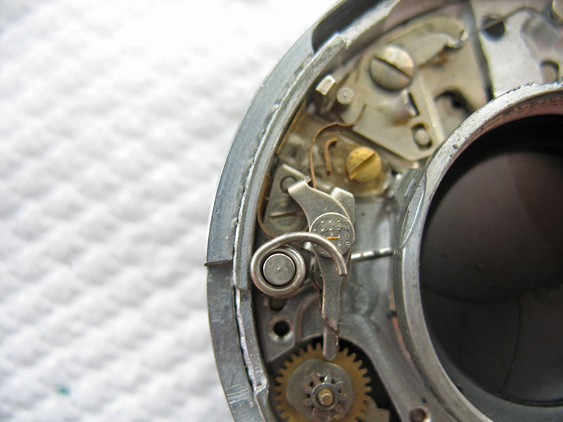
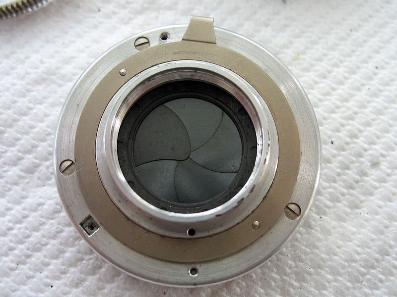
Here you can see the various parts that the speed cam acts upon.At 11 o'clock you can see the 1/500th second speed spring. At 10 o'clock you see the 'B' lever, and at 6 o'clock you can see the retard gear train.

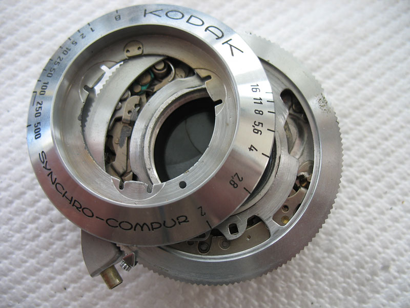
Lift off the speed cam to expose the working components of the shutter.
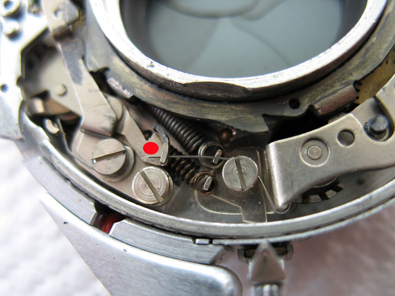
Unhook the end of the fine spring that activates the catch to hold the shutter cocked.
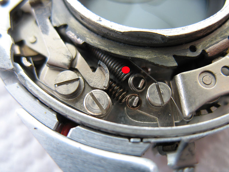
Unhook the end of the coil spring.This spring provides the main power to drive the shutter for all speeds, with the extra spring for the 1/500th second speed only being engaged when that speed is set by the speed cam.
Lift out the main ring.
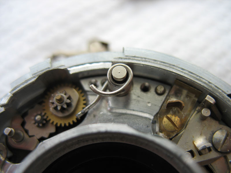
Note the shutter release lever and where its spring is situated, just tucked down into the shutter against the case.
Lift out the shutter release.
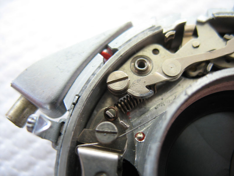
Remove the screw holding the spring and 'B' lever.
Lift out the lever, screw and spring.
Remove the screw at the lower end of the flash synch mechanism.
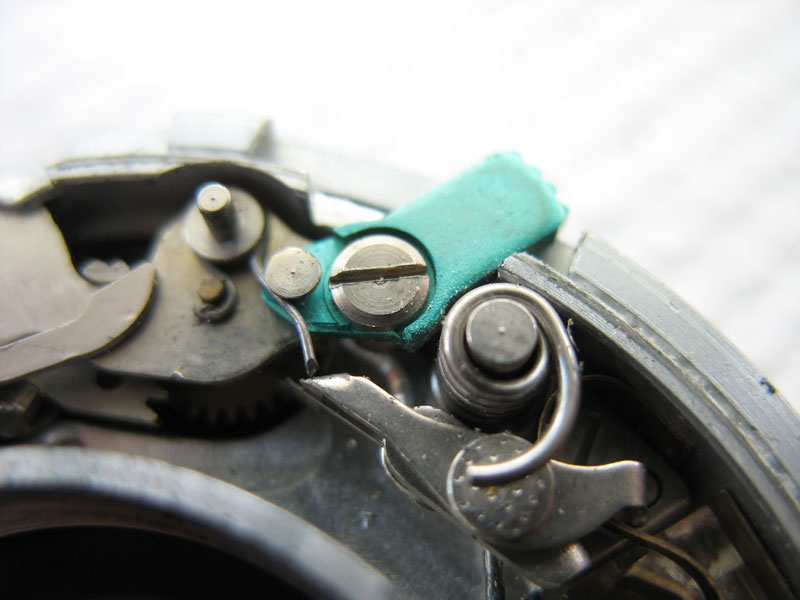
Remove the screw at the upper end of the flash synch mechanism.This screw also serves as the pivot for the M-X lever.
Note the difference in the two screws.
Lift out the top plate of the flash-synch mechanism.
Lift out the first brass spacer.
Lift out the second brass spacer.
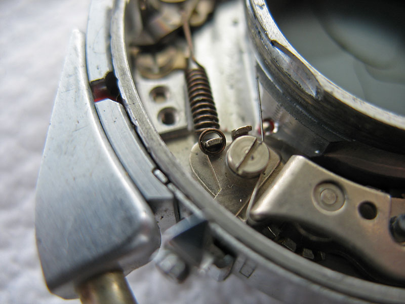
Unhook the end of the spring, but hold the spring down to stop it taking off into the distance while you do this.
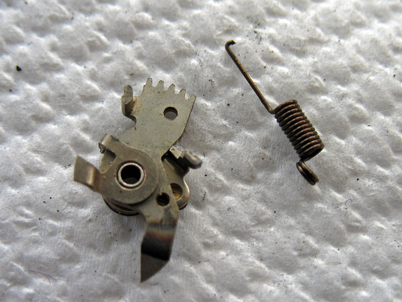
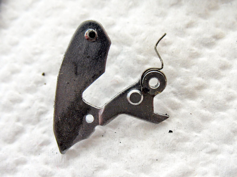
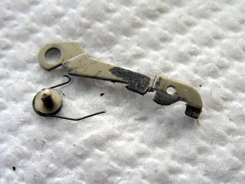
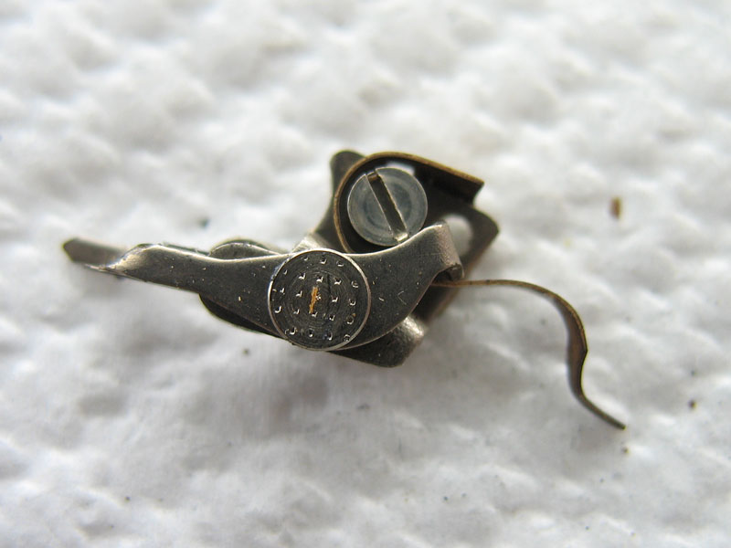
Lift out the spring and the lever. The lever is a two-piece arrangement, held together with a very fine spring, and it is awkward to reassemble, so take care not to let it come apart, and if it does, take care not to lose the components.
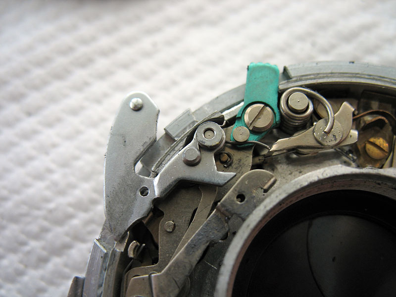
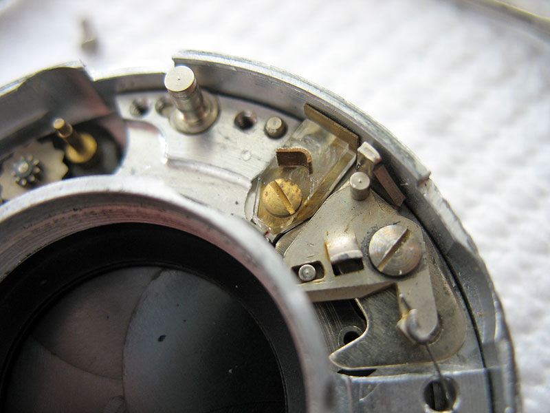
Note the position of all the flash synch components.
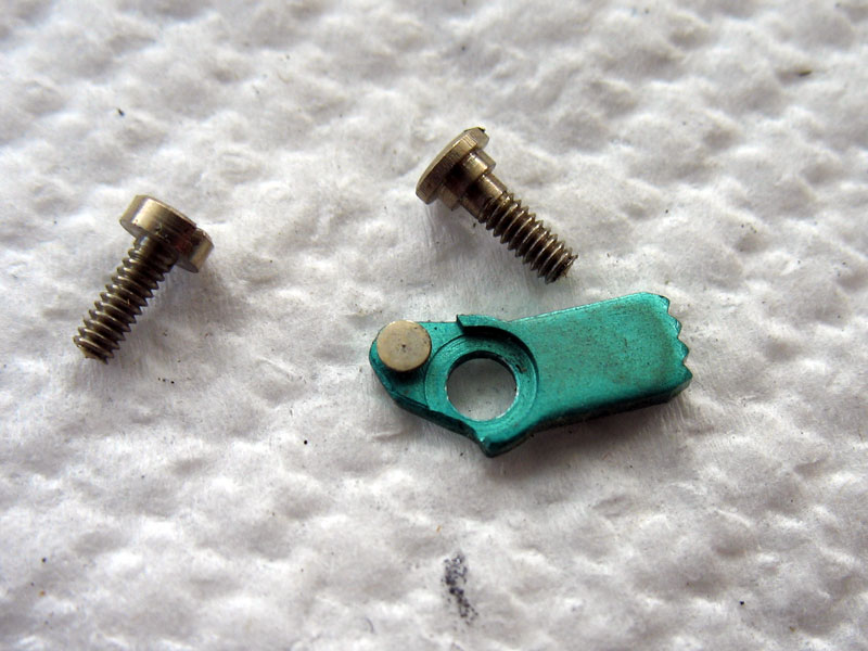
Remove the single screw and lift out the flash lever and the flash contact together.
Lift out the 1/500 second speed spring.
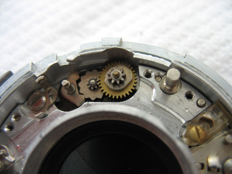
Lift out the synch gear on the right and pallet. The central gear is fixed and is not removeable.
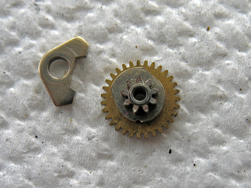
Close-up of gear and pallet.
There now only remains the flash terminal to be removed from the inside of the shutter. This component is moulded from a styrene-type plastic and is quite fragile. It is also easily destroyed with solvents, and so must be removed before any cleaning with solvent is attempted. It is best to remove it once the three case screws at the back of the shutter are loosened later in the process.
Remove the screw from the rear of the outer case.
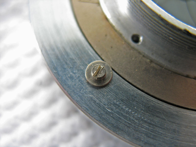
Remove the other screw. This one forms an alignment pin to prevents the shutter from rotating in the mount. Gently slide the outer case from the shutter.
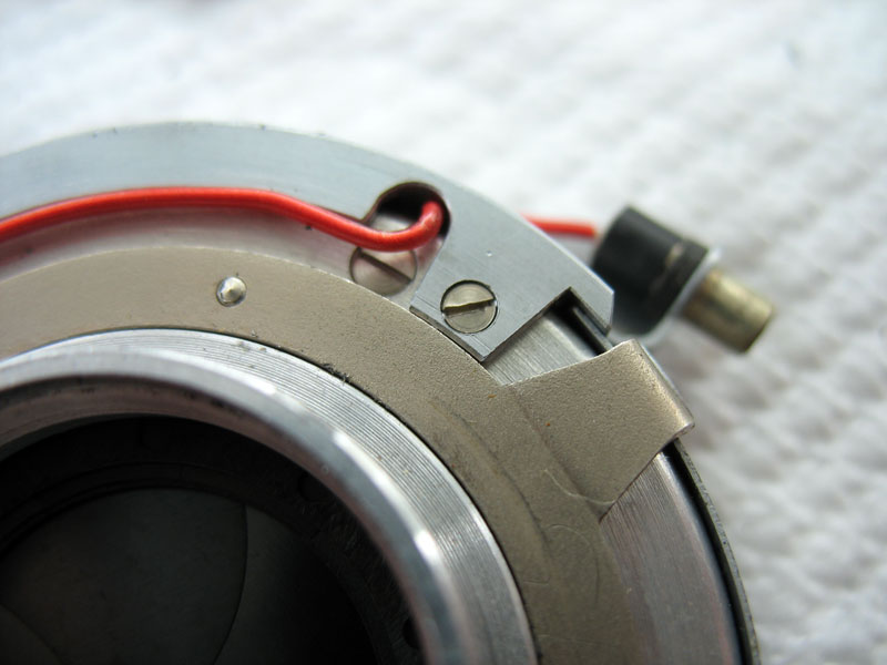
Unscrew the small black grub-screw that holds the flash synch wire and pull the wire out. Remove the screw completely. There is a tiny black plastic insulating slug under the screw that may, or may not fall out. Take care not to lose it.
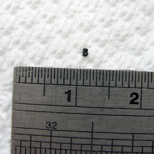
To impress on you the tiny size of that small insulating slug, here is a picture of it. The numbers 1 & 2 on this rule are centimetres, not inches.
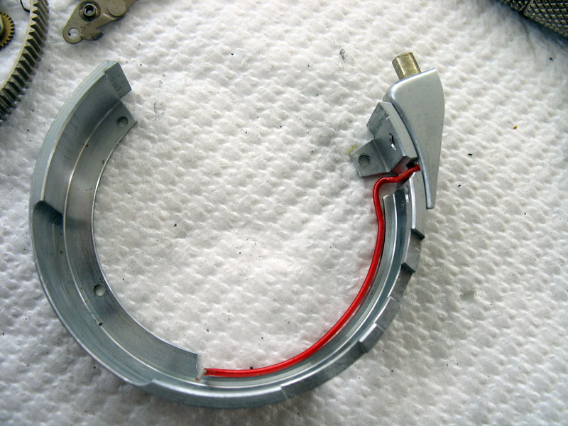
Here you can see the outer case and the channel inside where the curved cocking rack runs.
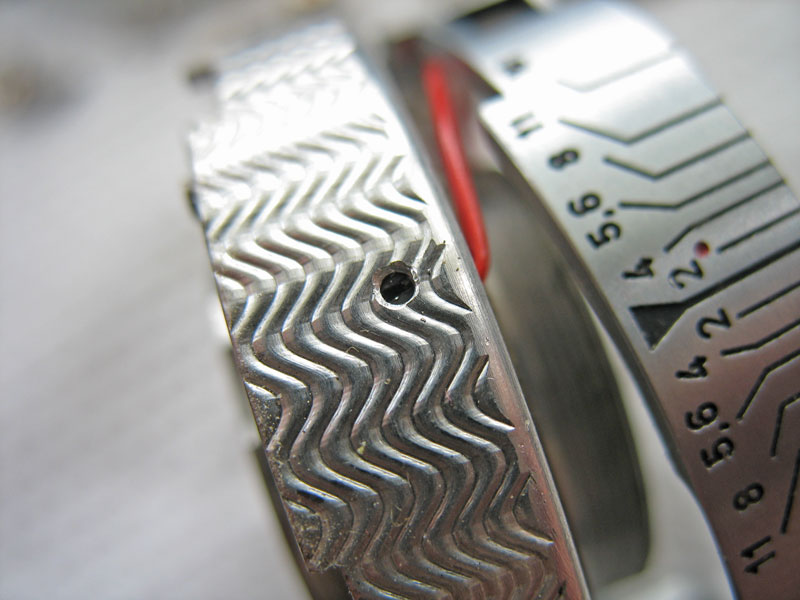
Pull out the thin curved piece of metal that gives the aperture settings their click-stops.
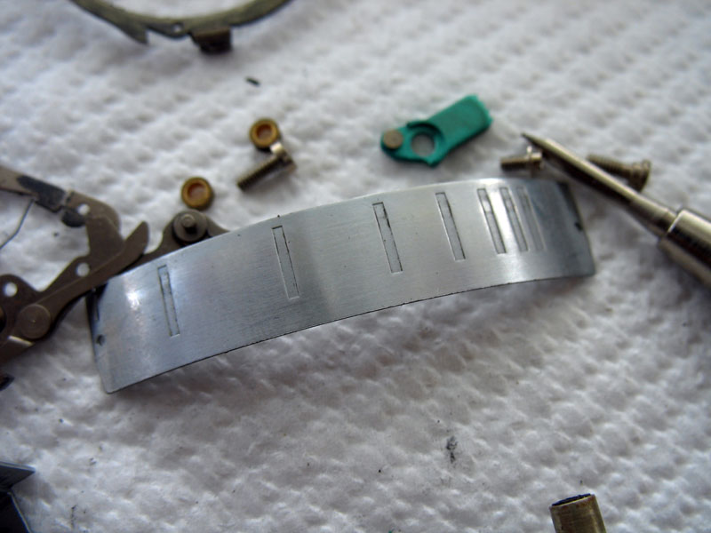
Note the spacing of the click-stop positions, close at the small apertures, further apart as the aperture is set larger.
Loosen slightly the three screws visible here at the rear of the inner case.
Remove the single brass screw holding the flash contact assembly into the shutter.If the flash contact assembly will lift out of the shutter now, then all well and good, otherwise leave it for the moment.The contact assembly is fairly delicate and easily broken.
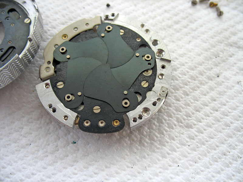
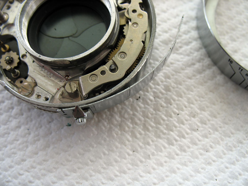
Turn the shutter back over, and remove the three screws completely and lift the case off the mechanism plate to expose the shutter blades.The case may be stuck, but a little poking and prodding with a screwdriver tip will free it.Keep in mind that delicate flash contact assembly.In case you were wondering why the retard gear train hasn't also been removed from the mechanism plate, this is for a very good reason. Getting the speed adjustments right is very awkward, involving moving the gear train slightly inwards or outwards at either end. Only rarely is there anything to be gained by removing the assembly for cleaning by itself. Cleaning can be acheived readily while it is still in place on the mechanism plate once the shutter has otherwise been disassembled.
Second part: Stripping down the diaphragm
Questions? Please contact Chris Sherlock