Chris's camera pages
Synchro-Compur shutter from a Retina IIIc
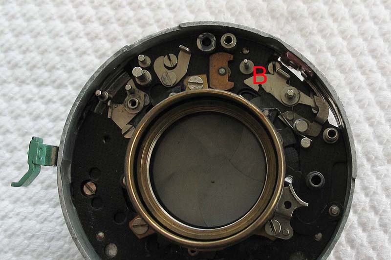
The mechanism of the Synchro-Compur shutter fitted to the Retina IIIc types looks daunting, but is easier to understand when broken into sections.The shutter seen here is only partly assembled with just the most basic components present to better show how the motion of the ring assembly which controls the position of the shutter blades functions.
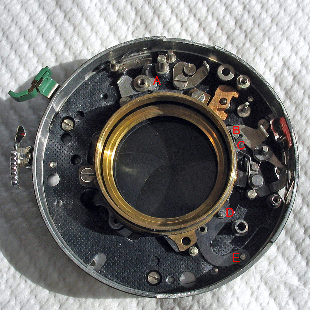
The shutter blades are opened and closed by swinging the ring assembly through a short arc anti-clockwise and back from the current closed position. The lever at A is part of the self-timer mechanism and blocks the rotation of the ring assembly if the self-timer has been set but has not yet completed its run-down. The lever seen at B is part of the flash synchronisation mechanism and when the flash synchronisation lever is set to M this part blocks the rotation of the ring assembly until the synch mechanism has run down. When set to X for electronic flash the lever at B is disengaged from the ring assembly. The spring seen here at C acts as a detent to keep the blades firmly closed until the ring assembly moves. It provides considerable resistance at the start of the movement, but little through the rest of the action. The points marked D and E are the posts on the ring assembly that the main drive assembly acts on as it rotates during the exposure.These actions can be seen in more detail below.
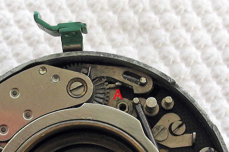
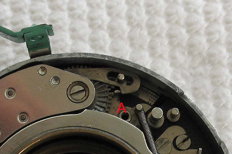
In these two pictures you see the self-timer fitted in place. In the first picture the self-timer is set, so the lever A that blocks the rotation of the ring assembly is hard over against the pin to its right being pulled by that spring. In the second picture the self-timer has run-down and has pulled the lever A back rotating the top towards the left, and you can now see some clearance between the lever and the pin to its right. At this point the ring assembly is no longer being blocked.
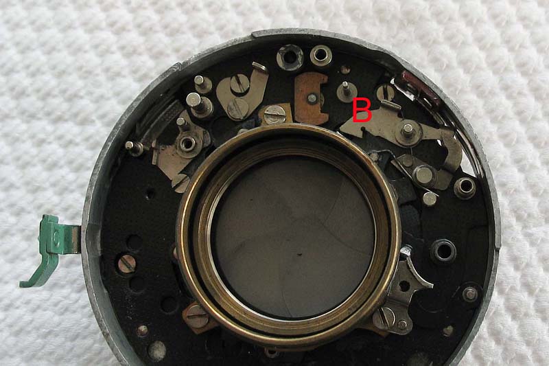
In the pictures below you can see the lever B that is part of the flash synch mechanism. In the first picture the synch lever is set to M, and the lever B is engaged with the ring assembly blocking it from rotating. In the second picture you can see the synch lever set to the X position and the lever B is swung clear of the ring assembly. The flash synch mechanism also acts on the lever B if the synch lever is set to the M position, but in these pictures those components have been omitted for clarity.
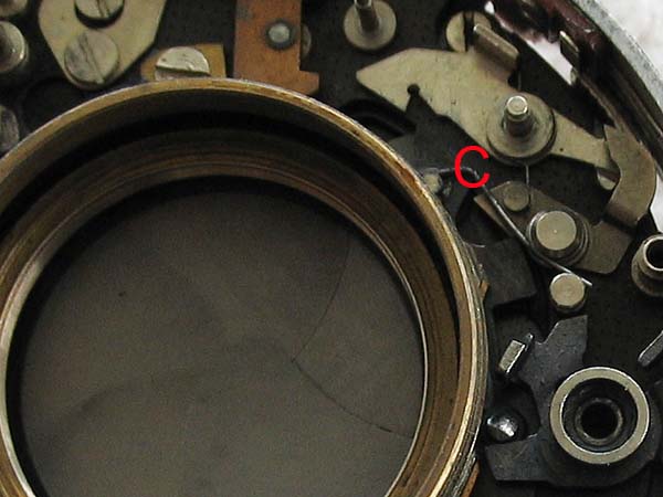
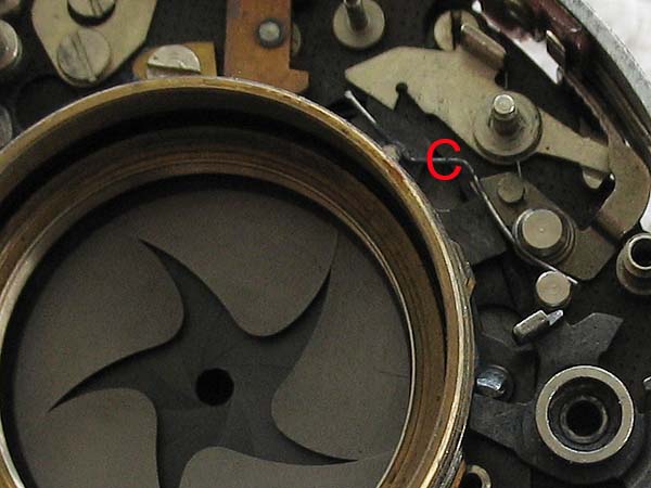
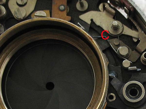
The detent spring C rides over a stud on the ring assembly and can be seen here in the first picture below with the shutter blades in the closed position, in the second picture with the blades in the partly-open position, and in the third picture with the blades in the fully open position, exposing the diaphragm.
The points marked D and E in the picture at the top of this page are the two posts that the main drive assembly acts on to rotate the ring assembly forward and back in order to open and close the shutter blades. The action of the main drive assembly on these posts is best illustrated in a brief video.