Chris's camera pages
Retina Reflex S strip-down continued...cleaning and reassembling the shutter, part four.
Before going any further with the reassembly it is essential to ensure that the shutter is working correctly, and that the shutter speeds are correct, as this is the last chance to make any adjustments.
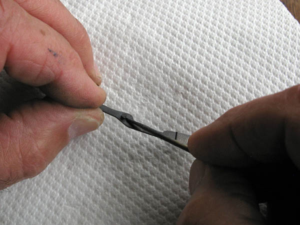
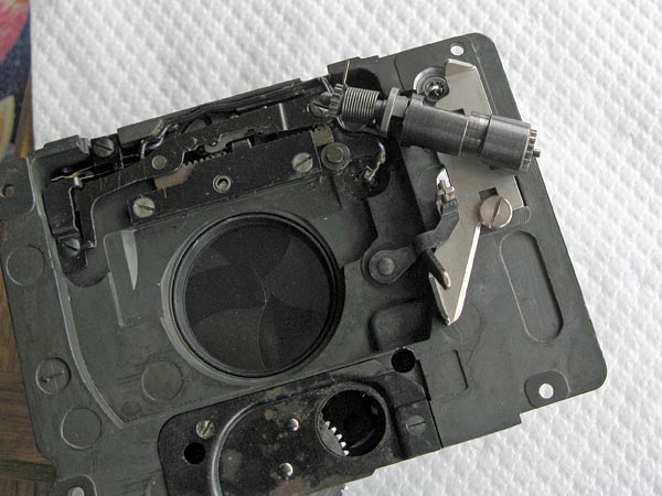
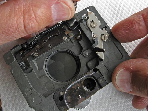
I have this tool made to cock the shutter from the rear by turning the shaft on the gear assembly, just as happens in the camera. You could do the same thing with pliers, but I wouldn't advise it. the shaft could easily become distorted and this would cause problems later.
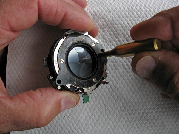
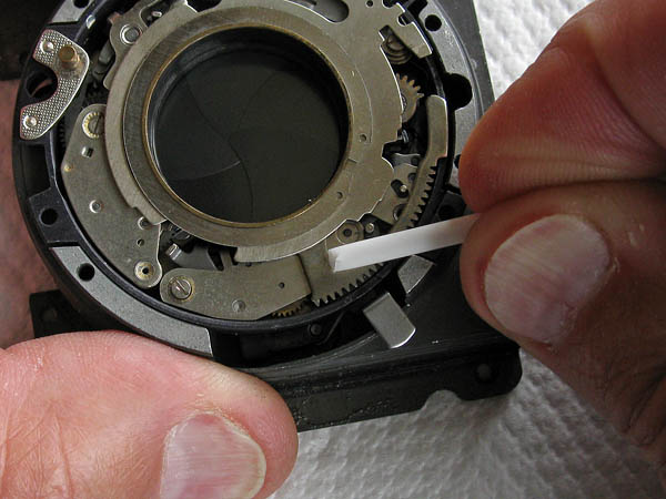
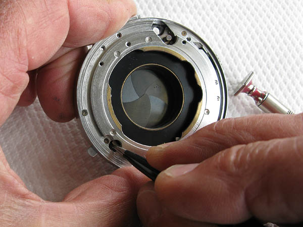
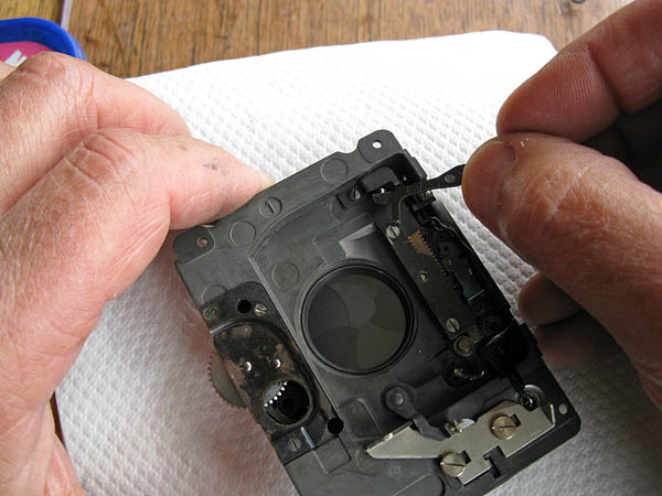
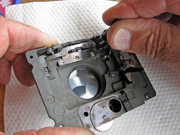
A good alternative is to cock the shutter by pushing the cocking ring with a suitable non-metallic tool. Here I'm using the shaft of a cotton bud, you might consider using a wooden skewer too, but you don't want to use a screwdriver, because you'd likely end up scarring the metalwork.
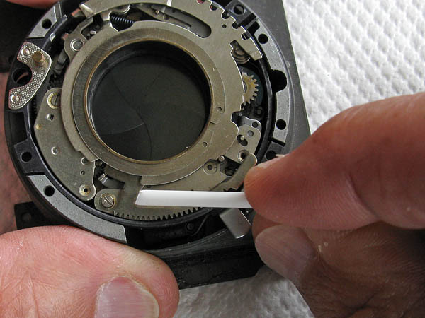
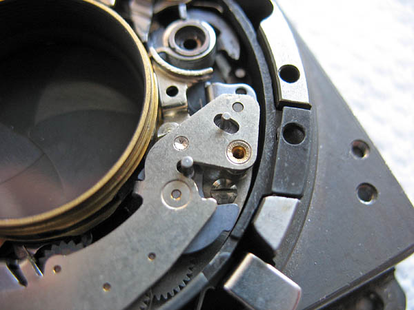
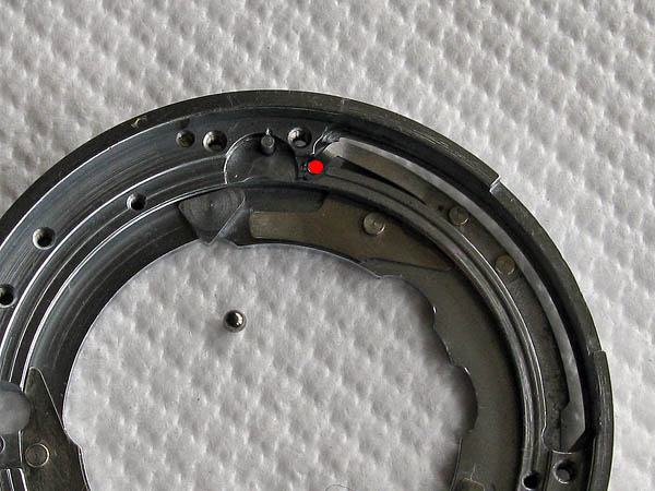
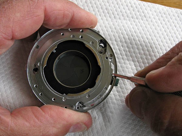
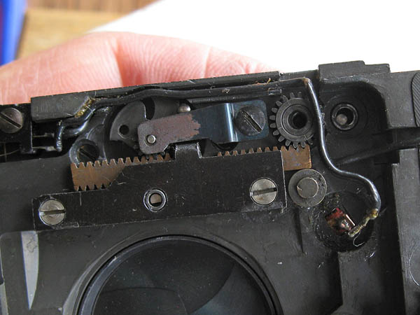
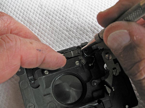
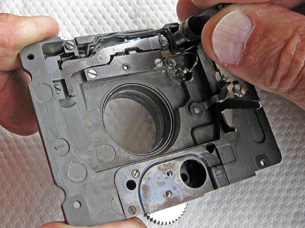
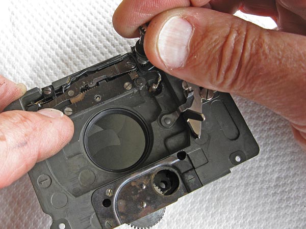
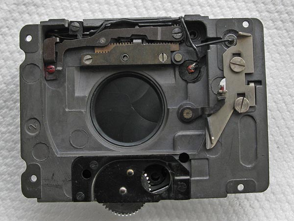
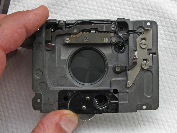
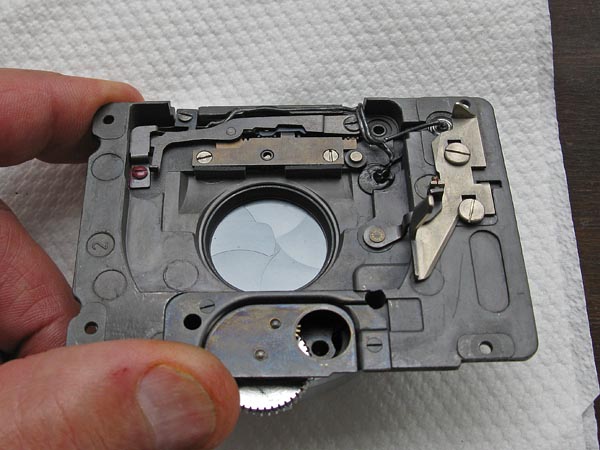
With the shutter cocked, set the shutter-speed ring to the 1/8 second position as in the photo below.The second picture shows all the speeds marked on a similar Synchro-Compur shutter. The position of the speed cam is always set against the main speed setting pin on the retard gear train.
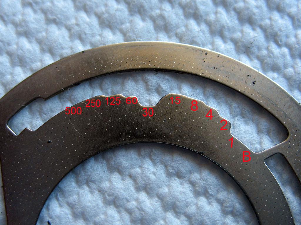
If you don't have access to a shutter-speed tester then you can always use a very old camera repairer's trick. The best speed to pick to set the shutter to is the 1/8th second speed. This is convenient since it is fairly easy to judge by eye and ear, although you do get better with practice. The shutter when set to 1/8 second should closely match the speed you get when you set the shutter to B, and then press and release the shutter release as quickly as you can. In other words, as quickly as you can bend and un-bend your index finger. You can see what a 1/8 speed looks and sounds like here..
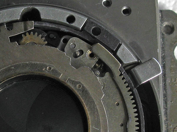
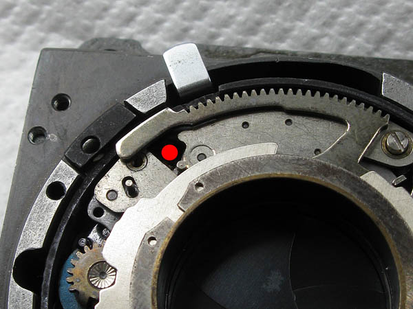
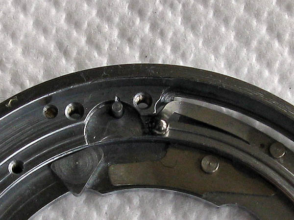
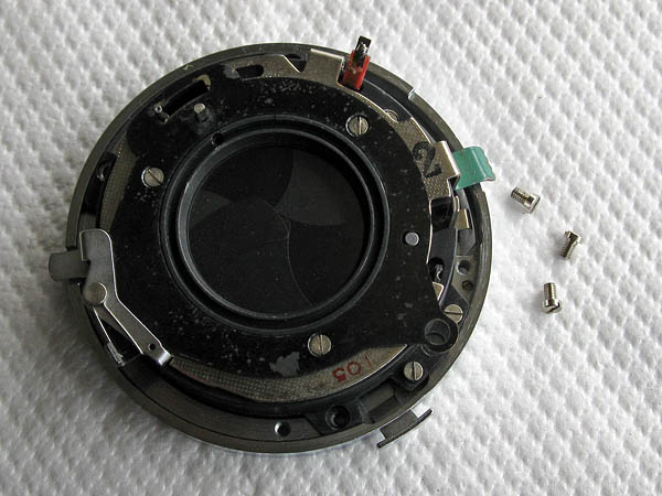
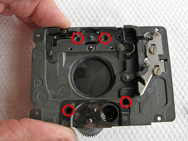
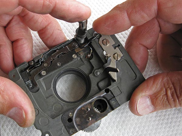
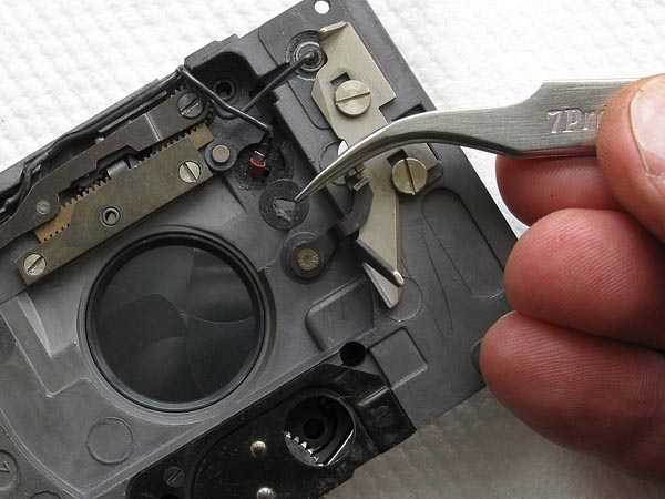
If the shutter is running too fast, you will need to cock the shutter, loosen the screw holding the retard gear train, and move the retard gear train inwards. If the shutter is running too fast, move the retard gear train outwards. A small shift makes a big difference, so don't be surprised if it takes you a while to get the adjustment just right.The screw you need to loosen is this one seen below, and if you are careful you can get to it without first removing the speed cam. It is down through the area marked with a red dot in the second picture.
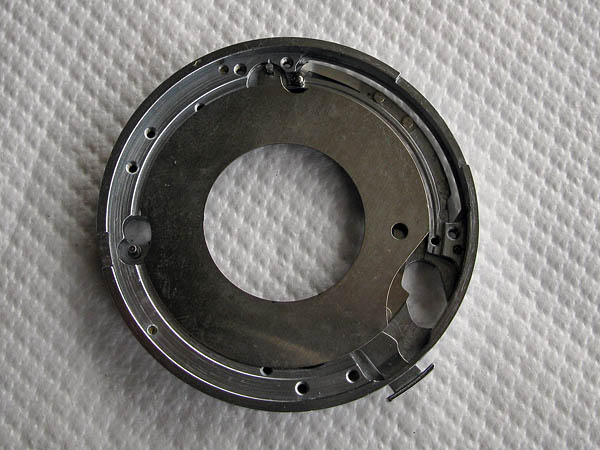
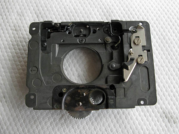
Clean all traces of old lubricants and dirt from the lens mount. Apply a tiny amount of lubricant to the ball detent spring to help hold the ball in place during assembly.
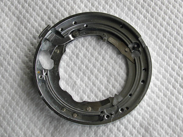
Place the ball in position. Place the cover plate in position. Note that the fork on the plate fits over the pin on the mount to locate it correctly.
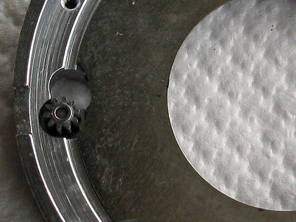
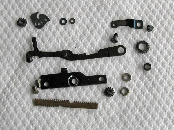
Clean the small gear and lubricate the hole lightly . The gear has a recess in one end to match the base of the post it fits over.
Lightly ubricate the speed cam where it will run over the ball detent.
Place the shutter over the lens mount. It can only fit one way to line up with the screwholes. Fit the three screws but do not tighten them right up.
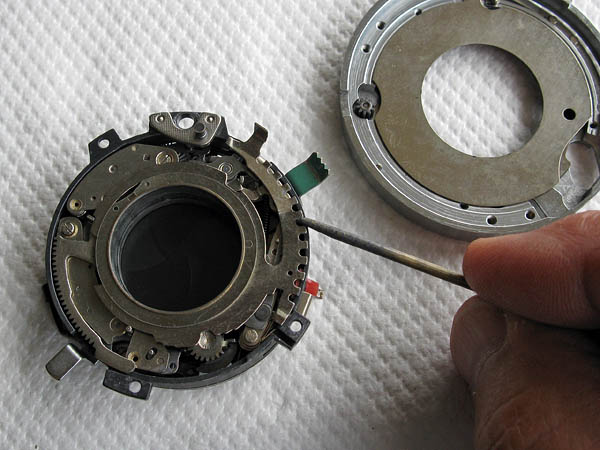
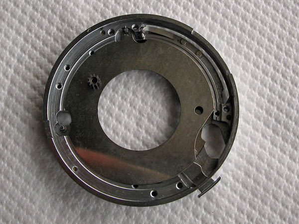
Turn over the shutter assembly and check that the cover plate is centred, that check that the small gear has correctly engaged with the teeth on the cocking ring by probing through the hole in the lens mount.
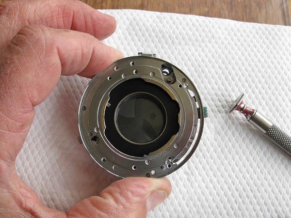
Check that the detent can be felt working correctly when you move the tab on the speed cam that protrudes through the front of the lens mount. If all is good, tighten the three screws holding the shutter assembly to the lens mount.
Clean the front assembly of all traces of dirt and old lubricants, and clean the components that will be fitted to the rear of the front assembly.
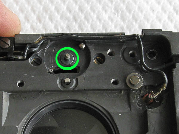
Fit the shutter assembly to the front assembly. Care should be taken to ensure that the flash synch contact passes throught he front assembly, and that the black shutter release arm on the front assembly is lifted towards the top of the shutter during installation otherwise it will block the shutter from fitting into the front assembly correctly.Once settled in place, install the four long black fixing screws in the positions circled here in red.Place the larger of the two thin washers over the pin circled here in green.
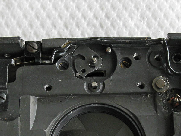
The next components are always fitted with the shutter in the un-cocked state. Check that the shutter is uncocked by pressing down the shutter release.Apply a little lubricant to edge of the cam, place it over the post and place the gear on top of it. Rotate the gear until it engages fully with cam.
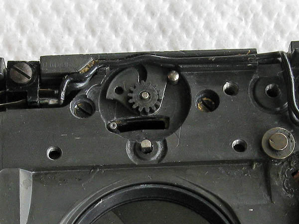
Place the small washer on top of the gear, fit the spring, and tighten the fixing screw.
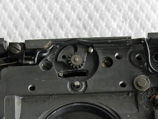
Fit the gear to the cocking shaft, and place the two spacing washers.
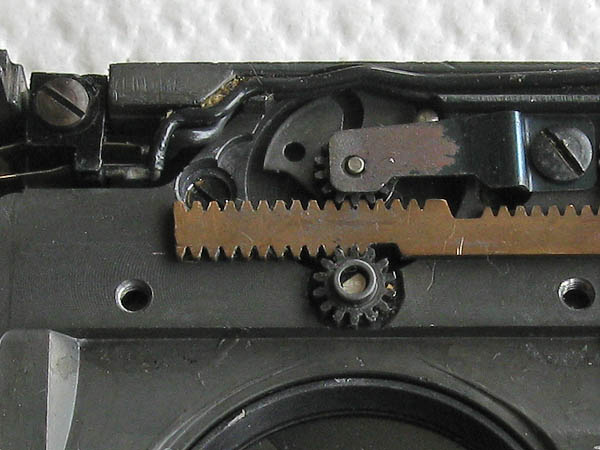
Place the toothed rack, described in the parts list as the 'rod'. Look closely at the position of the rack. Before placing the rack the cam should be rotated clockwise against the stop pin. The rod should be placed so that the lower tooth on the upper gear is engaged in the fifth V. The upper tooth of the lower gear fits into the first V.
Put a little bit of lubricant into the hole on the plate, this acts as the rear bearing for that gear, fit the screws and tighten.
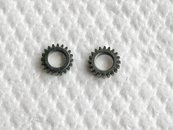
Note the gear (both sides are shown here) is not the same on both sides. The flat face goes against the casting.
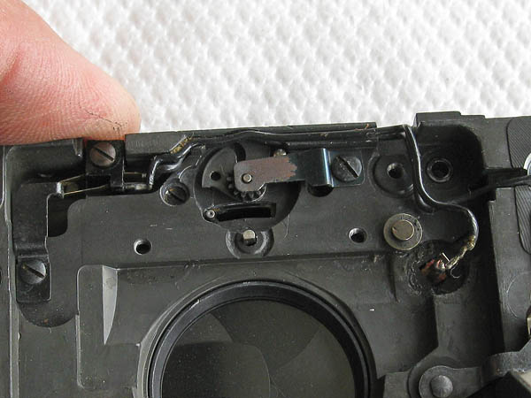
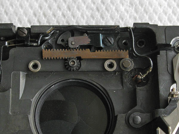
Lubricate the centre of the gear, fit the bushing, and place in position as shown.Lubricate the pin on the back of the arm assembly. This is where the arm is lifted by the movement of the rack (rod) to open or close the flash circuit.
Hook the arm into position, you may have to loosen the single screw holding that plate to make it easier. Remember to tighten it back up later.Fit the screw that acts as the pivot for the arm. Check it is centred correctly and that the arm is free to pivot.
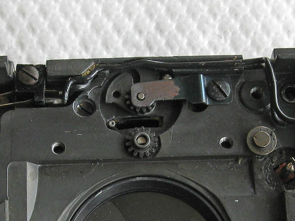
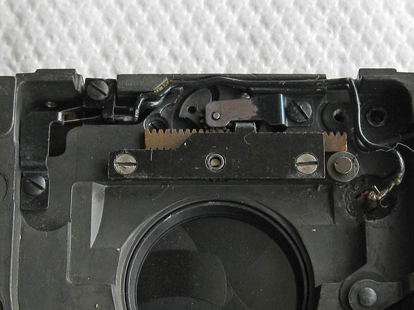
Fit the cam assembly onto the control shaft, this is used to cock the shutter.The arm on the cam assembly spring bears on the edge of the casting. Wind half a turn of tension on the cam and control shaft assembly before engaging it with the gear on the shutter assembly.
Rotating the cam and control shaft assembly clockwise will cock the shutter with the blades in the open position.Support the end of the cam and control shaft assembly with the tip of a finger and release the shutter by pulling the shutter release down.
The cam should rotate under spring tension and turn the gear, which moves the rod assembly. This will close the shutter blades.The rod is now stopped from completing its motion by lever assembly. Moving the arm upwards against the spring of the flash contacts will release the rod allowing the shutter blades to open and close for the set shutter time.
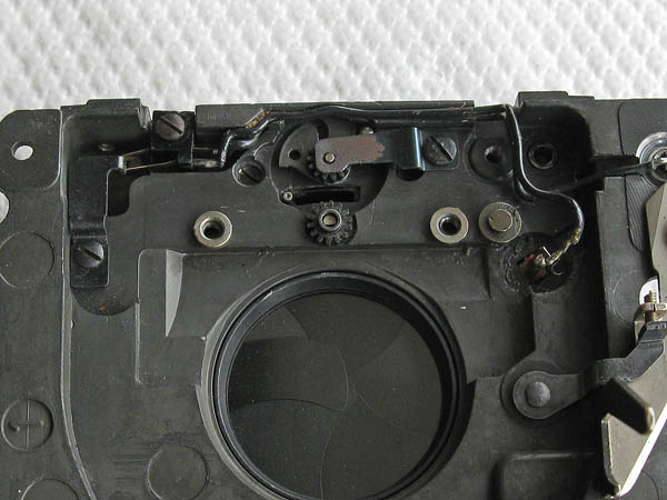
Clean any excess paint or adhesive from the insulating washer. Fit the washer in place over the flash contact, fold the contact down, and solder the flash synch wire.
Arrange the position of the flash synch wire so it is neatly back against the lever but leaves the edge of the gear uncovered.Cover the flash synch and its insulating washer with black paint. This will also serve to glue the washer in place.
This completes the work on the shutter assembly for the moment, the next task is to prepare the camera body for the installation of the shutter.
Next section: Assembling the shutter and camera body.