Chris's camera pages
How to strip-down and service the Synchro-Compur shutter on a Kodak Retina Ia or IIa camera: continued
Final shutter assembly
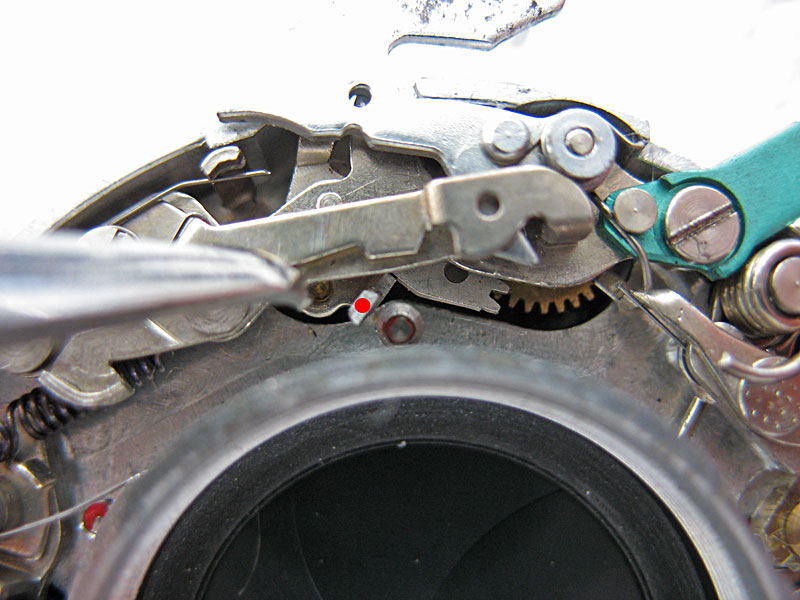
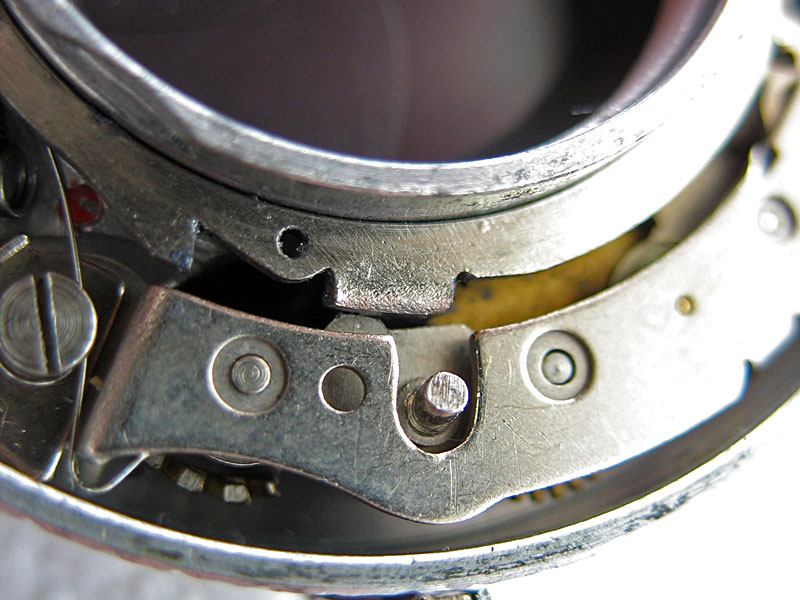
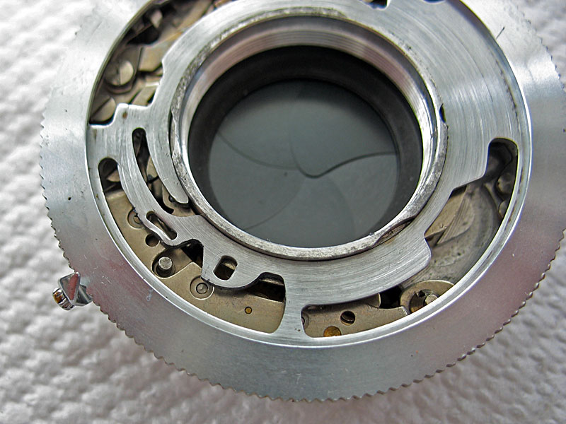
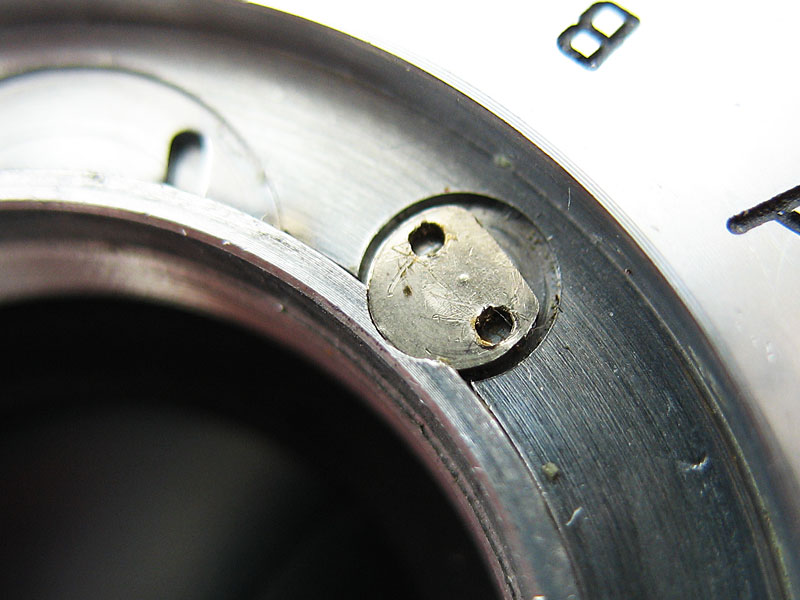
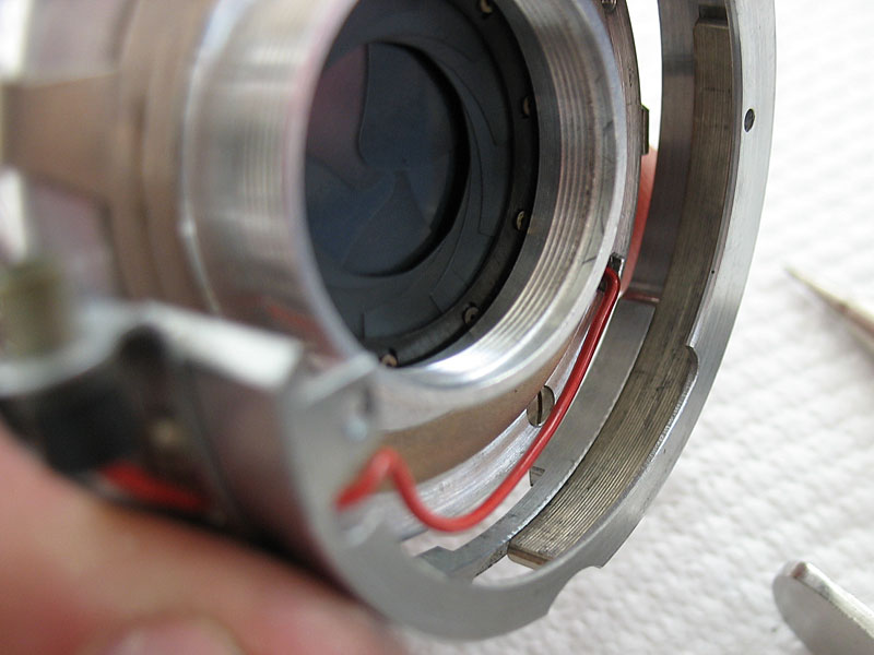
If you pull the 'B' lever back against its spring you can see the tab here marked with a red dot.This tab is pushed by the main ring when the shutter is cocked and 'arms' the flash synchro mechanism.This action also allows the lever that holds the shutter cocked to drop into place and hold the main ring in the cocked position.Push the tab with the red dot to the right with the tip of a screwdriver and it should lock in place. If you now press the shutter release lever the flash synch mechanism will release.Check the action at both the M and X settings.
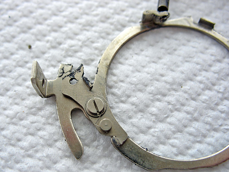
The main ring should be cleaned of any old lubricant.The ring has two important components, the main spring, which provides the motive power to drive the main ring, and the 'bird' pawl that pushes the blade operating lever to open the blades. Wipe a thin smear of molybdenum to both the inside and outside edges of ring, and apply a touch to both the tip of the bird's beak, and the upstanding tab at the other end. Also apply a touch to the larger tab on the ring itself.
Set the synch mechanism as desribed above and place the main ring on the shutter.You may have to feed the main spring into position under the 'B' lever.

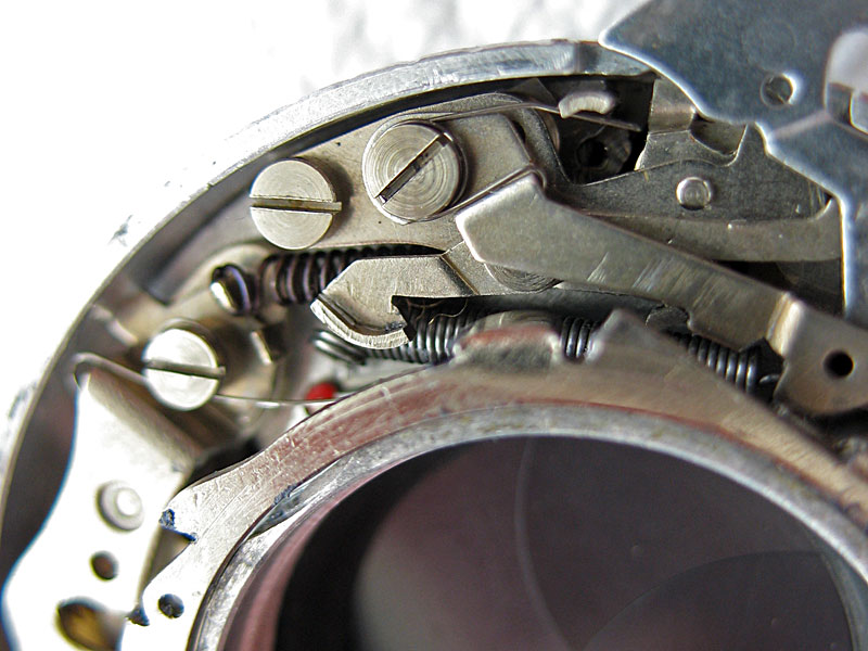
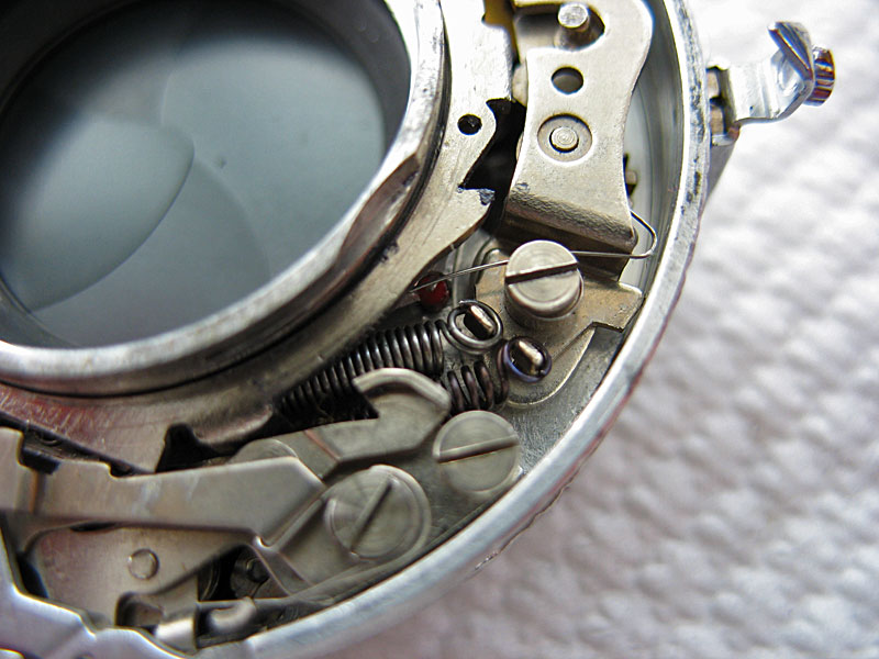
Check that the 1/500second speed spring is positioned as in the top of this picture.The bottom arm of this spring bears against a tab on the main ring, but is only tensioned when the top arm of the spring is held in position by the speed cam.
Pull the lever on the retard gear train outwards to allow the main ring to drop to the inside.
Pull the sector gear back to allow the main ring to fit to the inside.
Check that the main ring is sitting flat, you may need to push the 'bird' pawl across to drop into position corectly.Once the ring is seated correctly hook the end of the main spring over the post.
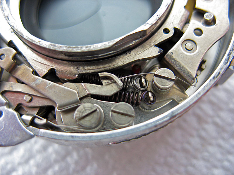
Fit the end of the fine latch spring in place.The shutter only needs the speed cam fitted now in order to function.Do not attempt to cock the shutter just yet.
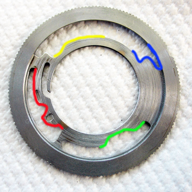
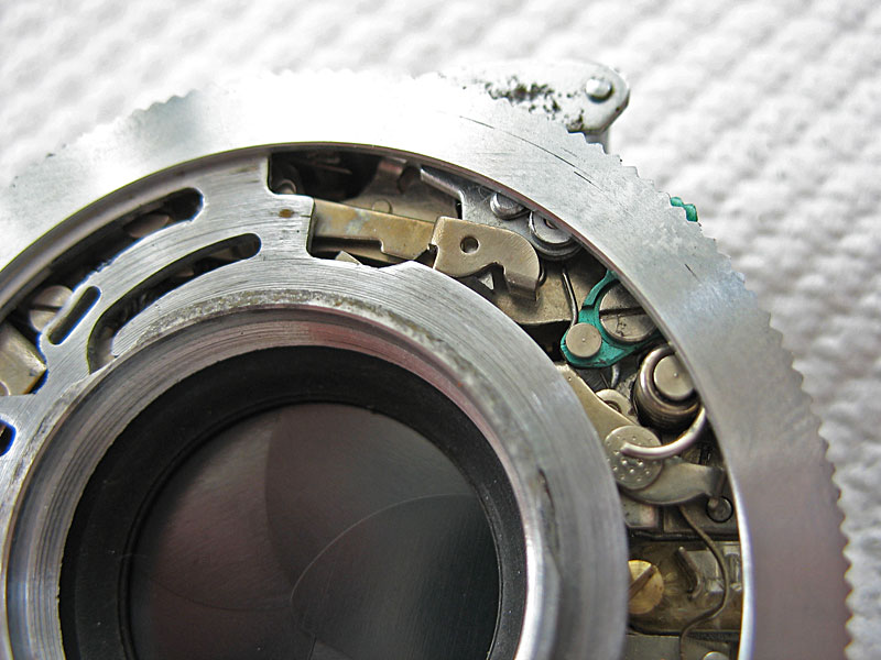
The speed cam should be cleaned and fresh molybdenum lubricant lightly applied to the inside edge and all the coloured areas in this picture.The red section controls the swing of the retard gear train, and so the shutter speeds.
The green section controls the pallet lever on the retard gear train, unloading it for the fast speeds and for the 'B' setting.The blue section loads the 1/500 second speed spring, and finally, the yellow section controls the action of the 'B' lever.
The green section controls the pallet lever on the retard gear train, unloading it for the fast speeds and for the 'B' setting.The blue section loads the 1/500 second speed spring, and finally, the yellow section controls the action of the 'B' lever.
Fit the speed cam. Make sure that the pin on the retard gear train is not trapped under the speed cam.
Check that the 'B' lever is correctly riding on the cam of the speed cam, not trapped underneath it.
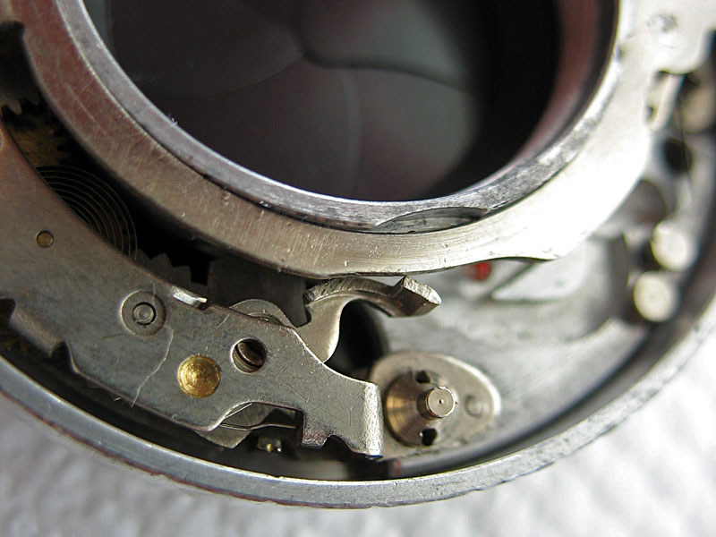
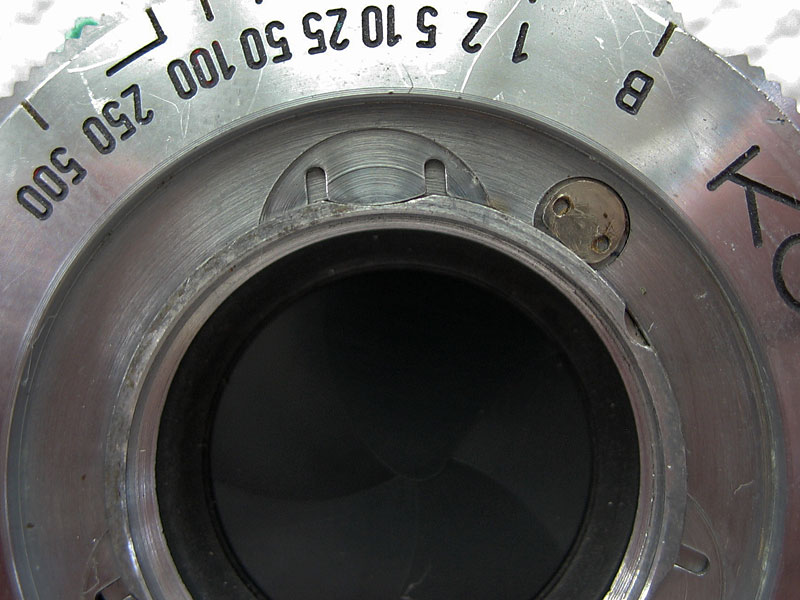
If the speed cam is set down snug against the shutter casing you can now check the operation of the shutter by first cocking it.This is done by simply pushing the external tab of the main ring visible here anti-clockwise until it latches.
Fit the front plate, the shutter speed scale goes to the top.
Rotate the plate clockwise, and turn the lock screw to fix in place.
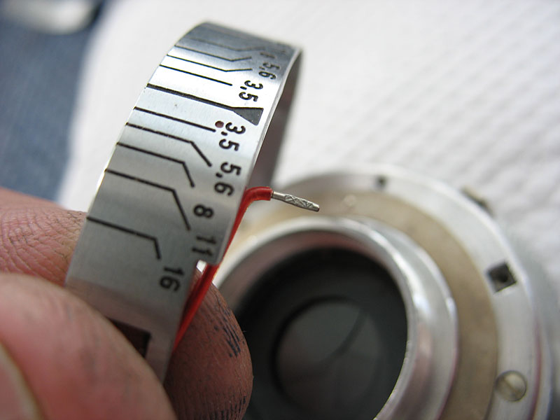
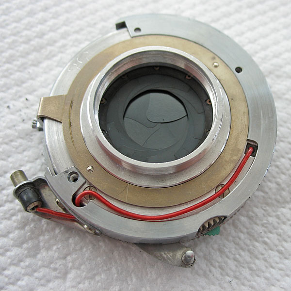
Clean the outer case carefully to remove all old grease and dust. Also clean the curved cocking rack and lubricate it very sparingly with molybdenum lubricant.Install the flash synch wire.
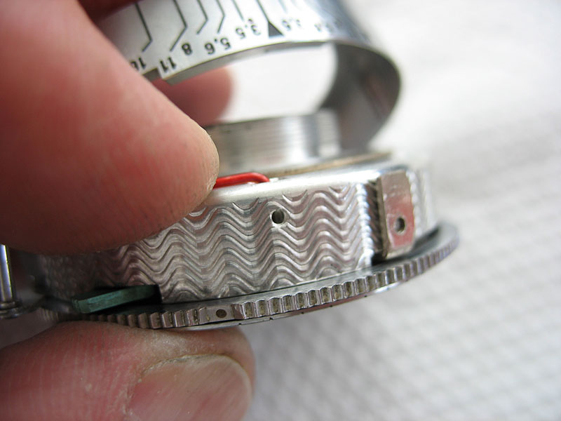
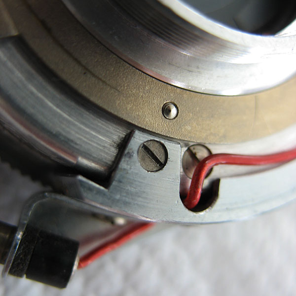
First fit the wire into the flash contact and hold while you drop the plastic insulator slug into the screwhole.
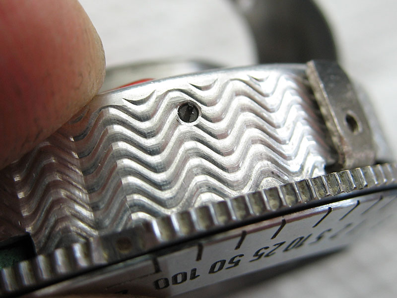
Fit the screw and tighten.
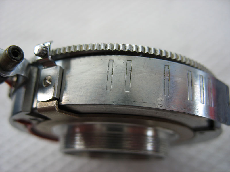
Cock the shutter to bring the protruding tab on the main ring to the top of the shutter and install the curved cocking rack in the outer case.
Fit the outer case over the shutter and align the two holes. There is nothing to go in the third hole, and never was.
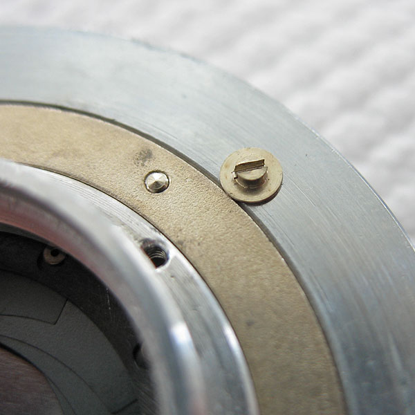
Fit the first screw. This one forms the post that prevents the shutter from rotating in the mount.
Fit the second screw near the synch terminal.
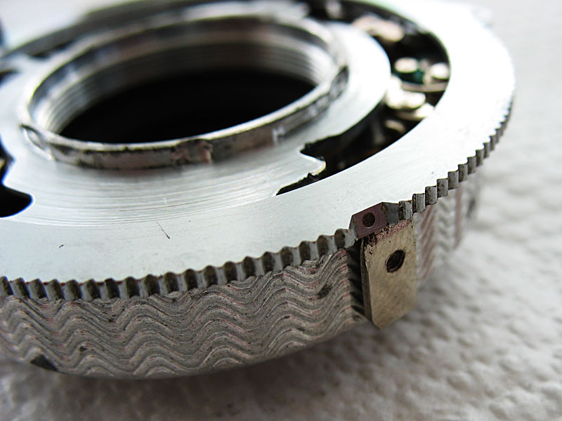
Slide the diaphragm pointer across to the maximum aperture position and feed the scale click-stop plate into position. The end fits in under a recess in the outer case.The spacings of the click-stop grooves are further apart at the large aperture end of the scale.
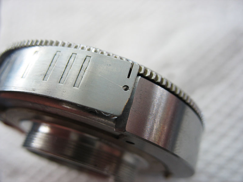
Push the other end of the click-stop plate and spring it into position.
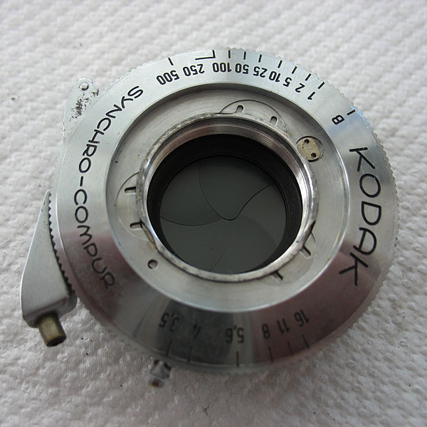
All done.
Questions? Please contact Chris Sherlock