Chris's camera pages
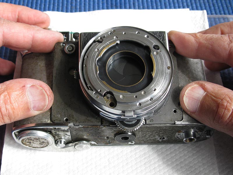
Retina Reflex S strip-down continued: Assembling the shutter to the body.
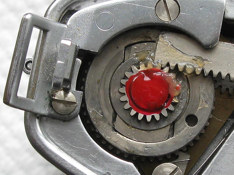
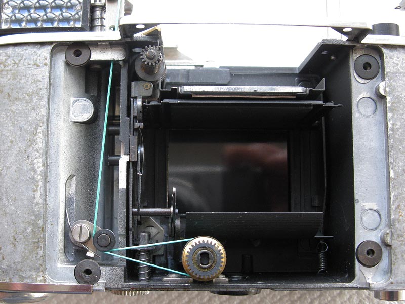
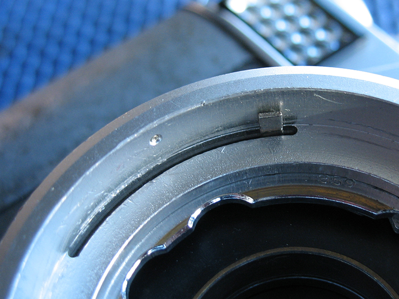
The first task is to lock the screw on the top of the film advance shaft with some lacquer to stop it working loose. Cheap nail varnish is just the thing for this job. The lacquer should seal the gap between the screwhead and the gear, but not run over the gear teeth.Lightly lubricate the shutter release shaft and the film release button assembly. Fit their springs and place both in position. Note that the shutter release shaft has a notch on side of the plate that aligns with the edge of the upright post holding the meter cord pulley.
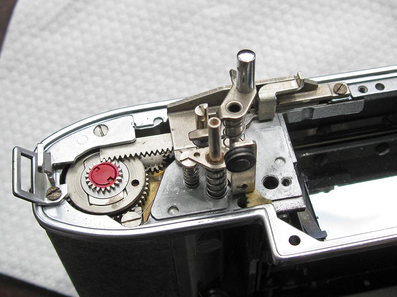
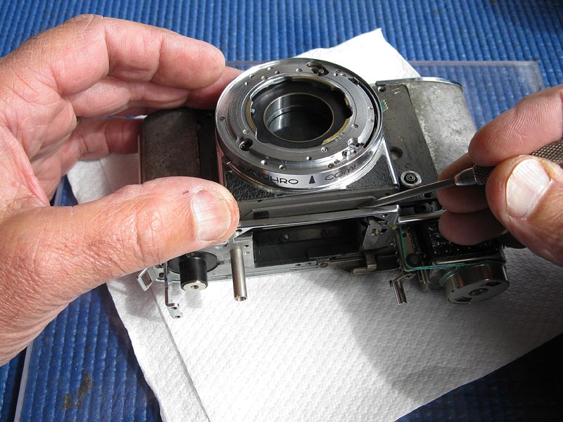
Apply some grease to the rack and gear, some should be applied to the top of the film advance to lubricate the clutch.
Place the meter in position. It has short plastic pins moulded on the base which need to align with the matching holes in the top casting. The tab on the end of the meter should hook under the strap lug as shown. Check that the film release button assembly is not jammed against the meter.
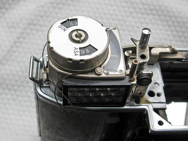
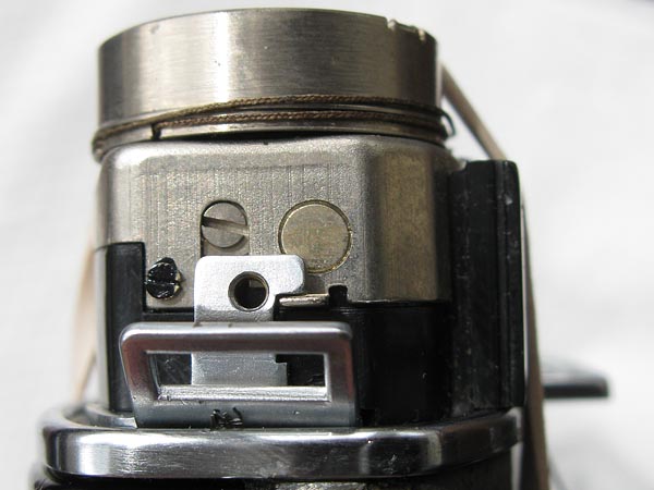
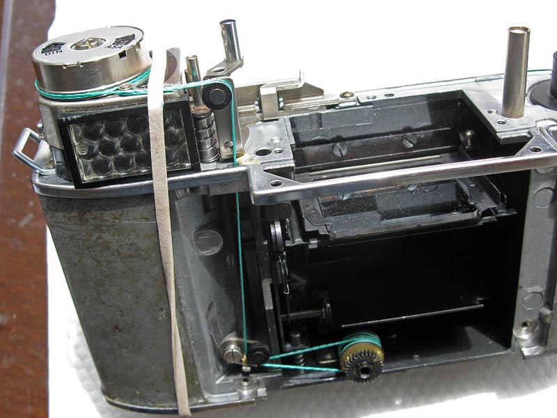
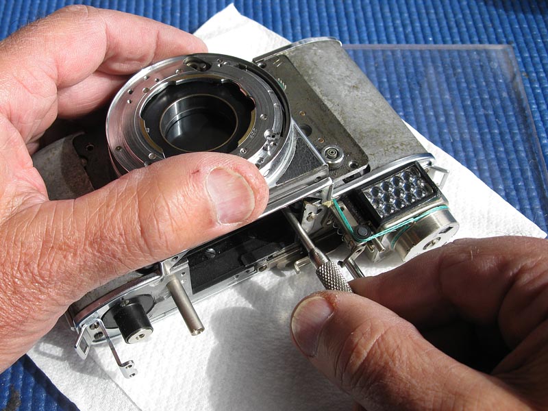
The meter coupling cord should be installed as shown in the service manual. You can find a copy of the Retina IIIS service manual here. The Retina IIIS uses the identical meter setup. Remember to lubricate the inside of the lower meter drum before installing it. Take great care to follow the schematic. If you get the cord running over the wrong pulleys anywhere the meter will revolve in reverse. Here I have replaced the original cord, since it was looking worn, although it may not have been in any immediate danger of breaking.Notice I have used a rubber band here to hold the meter in place. This will help keep things in place during the assembly.
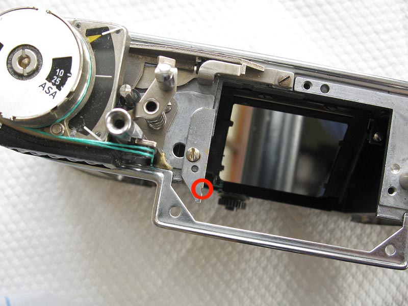
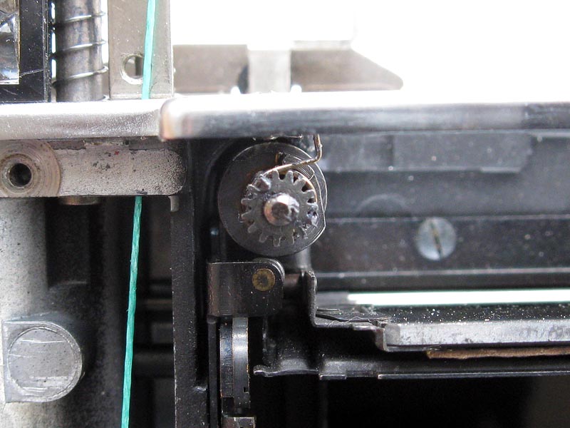
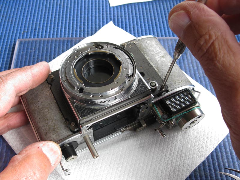
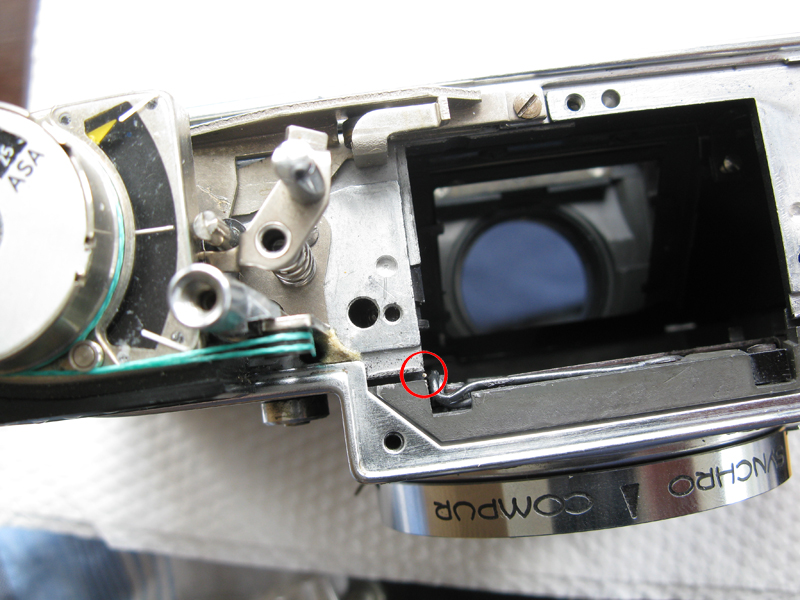
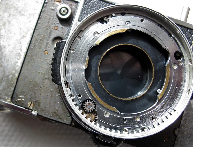
Kodak made a special tool to do this job, which is to hold the tension on the spring fitted to the cam, and doubtless their tool looked better than this little bracket made from some scrap. This does the job however. Notice the notch filed into the edge circled here in red. This notch holds the spring.Take care not to use a long screw to hold your bracket, or it may foul the control shaft.
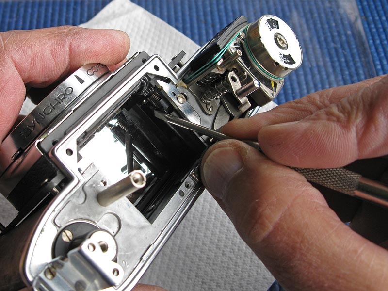
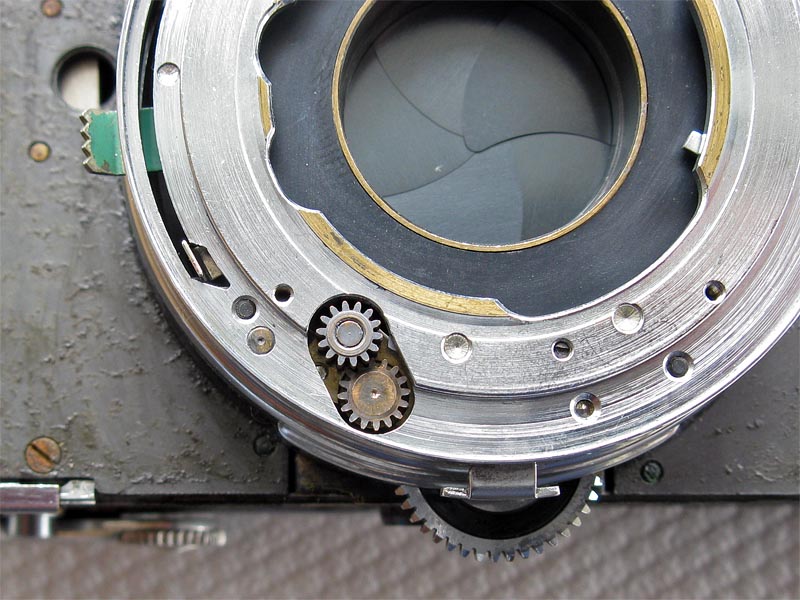
The surface of control shaft should lubricated lightly with molybdenum where it shows shiny rub-marks from wear. Apply a little grease to the gear and insert the control shaft. It should be engaged with the shutter-cocking rack and make sure that the angle is as shown. Take extra care to avoid touching the front surface mirror as you install the control shaft.
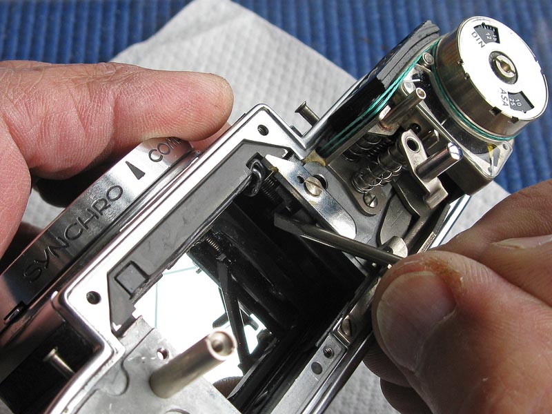
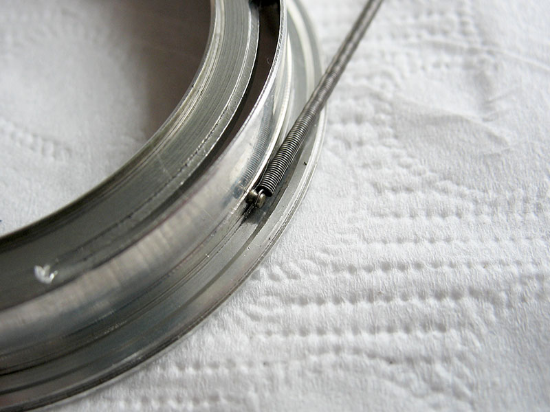
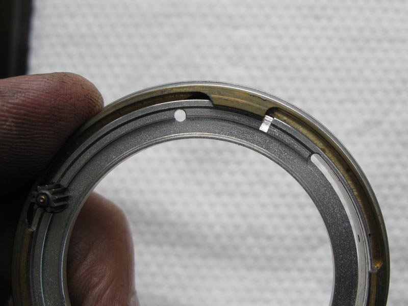
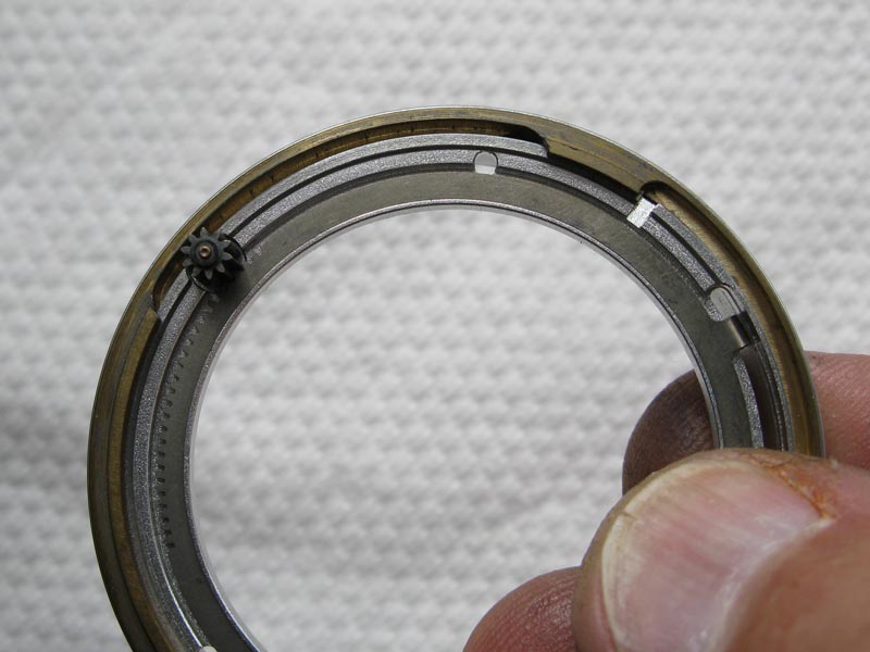
Lubricate the inside of the cam with a little moybdenum smeared on a toothpick and fit over the control shaft. Rotate the cam clockwise. The spring will probably sit somewhere like the one in the first picture. You must wind the spring clockwise approximately 1.25 to 1.5 turn and hook the tail of the spring in the notch on that bracket. The tension on the spring drives the gears and advances the position of the rod assembly as it controls the movements of the shutter components.
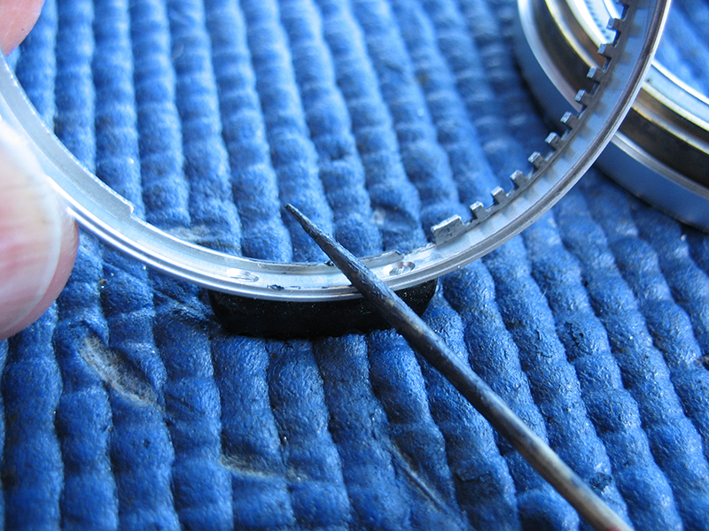
The spring washers that sit between the front assembly and the main body casting will number either eight in earlier examples or twelve in later production. They are used in groups of three at each of the fixing screws for the front plate, arranged like this )(), or if there are only eight arrange them llike this (). They are entertaining to place, and it is even more fun to try and replace the front plate correctly without disturbing them, but it certainly can be done. Many repairers resort to sticking them together with wax, grease or glue.
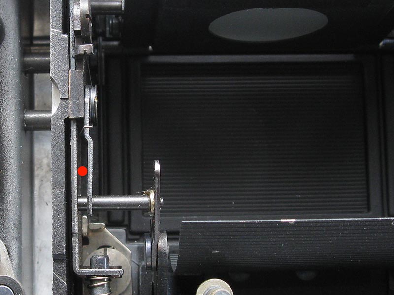
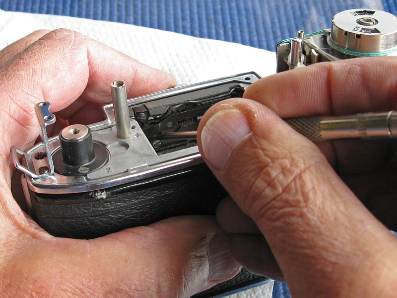
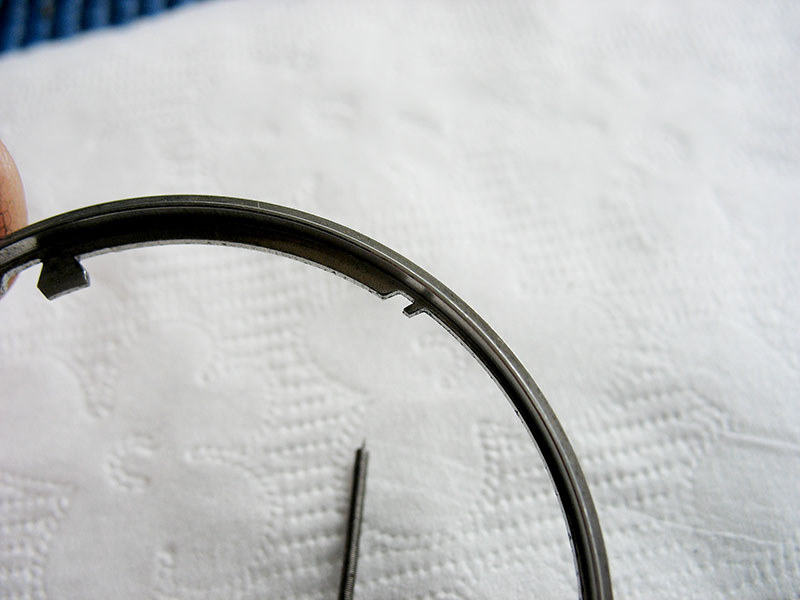
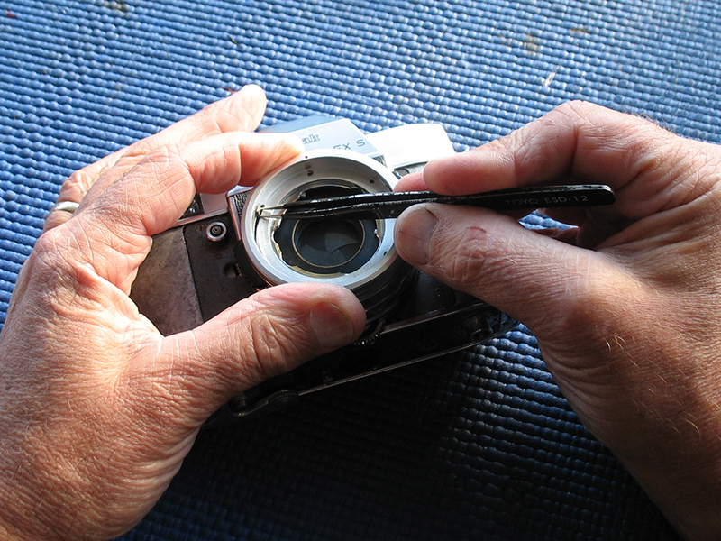
Before fitting the front assembly take note of where the shutter release lever on the back of the front assembly is to go. It has to fit into the gap between the levers here marked with a red dot.
Carefully lower the shutter onto body, starting at the bottom end, this should settle over the lower meter cord drum.
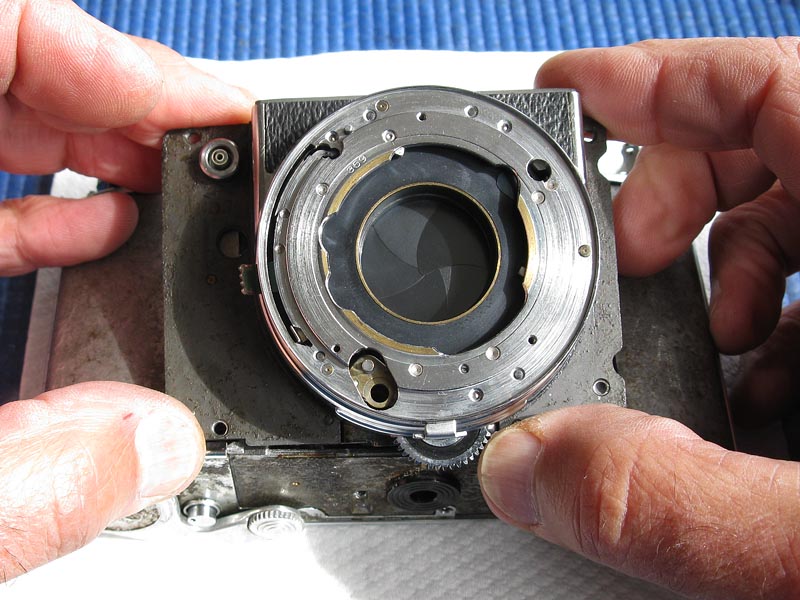
Rotate the camera, and gently pull the chrome trim back so that the front assembly can drop further into place.
You will need to depress mirror slightly to clear front casting. Press on the area beside the mirror, not on mirror itself.
Ideally, you loosely insert four long screws to keep the spring washers in place. You might get by by placing thin brads through the holes instead.
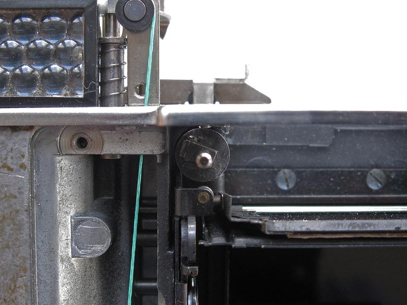
Push the control shaft gently across towards the exposure meter end of the camera into its correct position.If you are very lucky the gear teeth will drop into position, otherwise it will be like this one, where the front assembly is obviously not fully home.
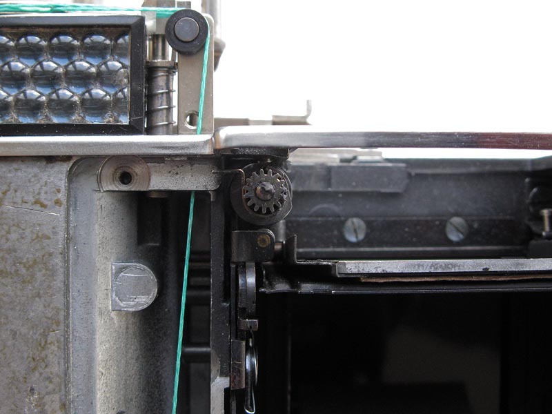
Here I have gently pushed the rod assembly towards the exposure meter end of the camera to align gear teeth. This is done while keeping light pressure on the front assembly. It is easy to feel the gear teeth align and the front drop fully into place.Note that only a very small movement of the rod assembly is needed, the rod will only need to be moved less than the width of a tooth to allow the gear teeth to engage.
Swinging the film advance lever gently to cock the shutter should leave the shutter blades completely open. If the shutter only opens as far as this, then the timing is not quite correct, the shutter is not advanced far enough relative to the position of the cam in the camera, and so you will need to attempt to refit the shutter again. Alternatively, if the film advance lever stops before reaching the end of the advance stroke, but the shutter is already fully open, then the timing is also incorrect, and the shutter is advanced too far relative to the cam in the camera. Removing the front to try again will likely require recovering the washers from wherever they have fallen, since they have a habit of falling into the body, and also checking the position of the cam, which will probably need to be put back in position and the spring retensioned. Patience and persistence are usually required.
If, miracle of miracles, the shutter opens completely, locks into the open position, the mirror stays down in the viewing position, and the shutter fires correctly when the shutter release is pressed, you are now on the home straight. Refit the proper screws one at a time to fix the front plate. Do not tighten them fully at this stage.

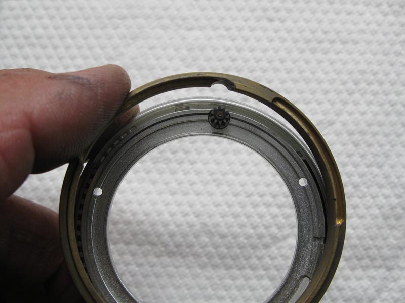
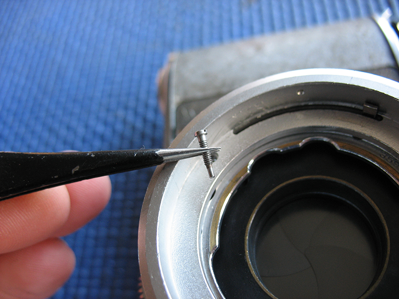
You can now refit the pinion assembly and matching gear. The pinion assembly has two small flats on the end of the shaft which fit into the slotted hole on the drum assembly for the meter coupling cord. A smear of molybdenum paste on the shaft of the pinion, especially at the end will help here. The pinion should seat firmly down in the recess. Tighten the screws firmly. The dished washers act to give some spring action so that you can position thefront plate evenly and the correct distance from the film plane. Ideally, you'd have a ground plate that the the film rails sit on and a dial indicator which you use to check the distance from the front of the lens mount to the film plane. In practice, I have found that tightening the screws right up, and backing them off about an eighth of a turn will do the job.
You can remove the bracket holding the cam spring. The end of the spring is now held by the casting.
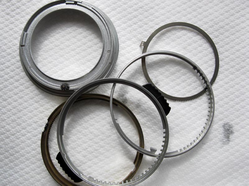
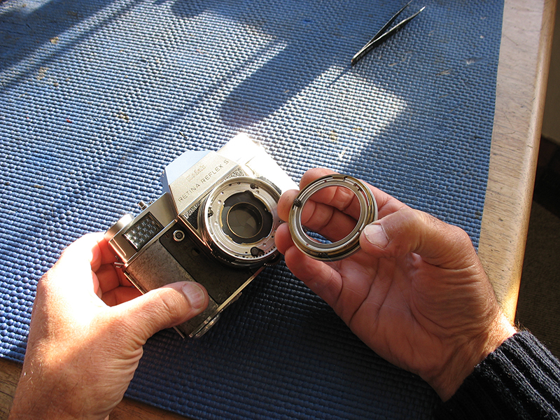
Clean the shutter-speed and aperture settings rings and their matching components. These parts are often gummy with the old grease and the ground-in dust that has found it way in between the gaps.
Start the assembly by hooking the spring back onto the post on the front component if it has come apart during cleaning.
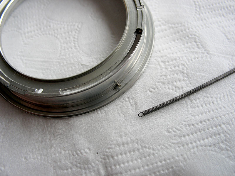
Connect the other end of the spring over the hook on the aperture ring.
Turn the shutter speed ring anti-clockwise and engage the tab in the slot in the front component. At this stage I usually sprinkle a little graphite powder into these components and work the aperture ring backwards and forwards to distribute it. Blow out all the loose graphite.
I give a very light smear of molybdenum to the brass component before I fit it. The cut-out in the brass component clears the pinion on the front component.
Rotate the brass component to align the end of the milled slot in the brass with the slot in the aluminium front component as shown.
The ring that opens the diaphragm on the lens is fitted into place. Note that the third tooth on the rack aligns with the centre pivot. There should be a noticeable gap between the tab on the ring and the end of the slot in the front component. Put this assembly aside.
The cut-out in the shutter-speed setting ring and the notch beside it where the shutter-speed tab in the shutter can be seen here should be lubricated with a little molybdenum. The tab in the shutter stays in the notch in the shutter-speed setting ring at all timed speeds, but disconnects from the notch and moves in the cut-out when the shutter-speed setting ring is moved between the B position towards the end of the green numbers, the whole seconds positions. Note that the shutter should be at the B position at this stage.
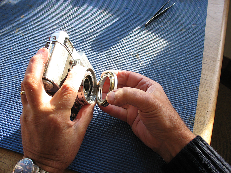
Without disturbing the position of the various components in the front ring, fit them to the shutter.
This is best acheived by holding the camera on its end.
If required, wiggle the tab to align the diaphragm opening ring with the driving gear in the shutter. The tab should sit much as in the second picture, with obvious small clearance at the end of the slot.
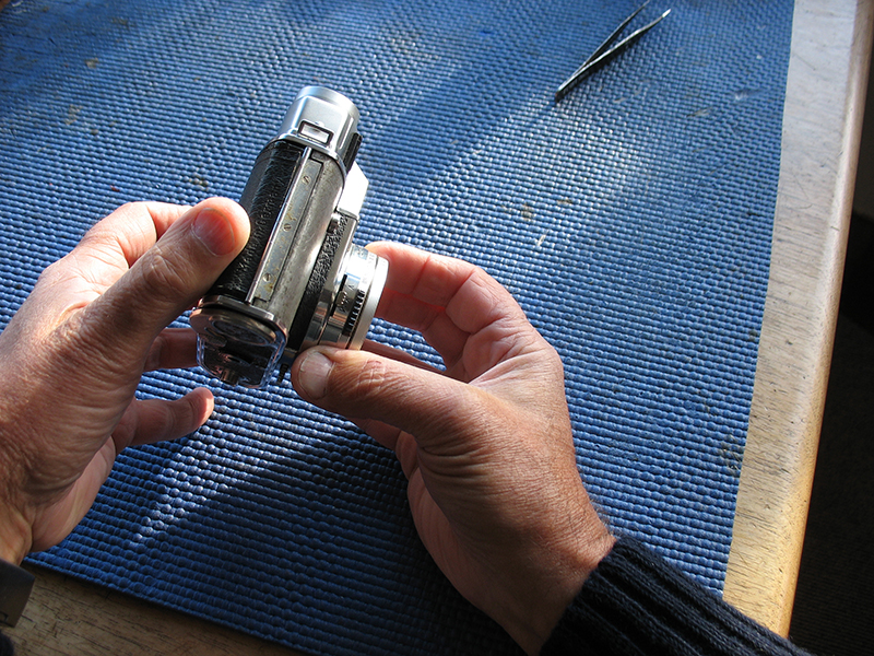
With the front rings are fitted back into position correctly, you should refit the three screws holding the front components to the shutter body. Note the position of the longer screw.
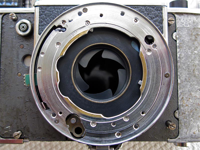
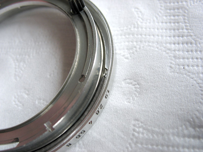
The shutter-speed setting ring should rotate smoothly between either end of its travel, from the Green 250 seconds mark at f/22 through to 1/500 second at f/1.9.
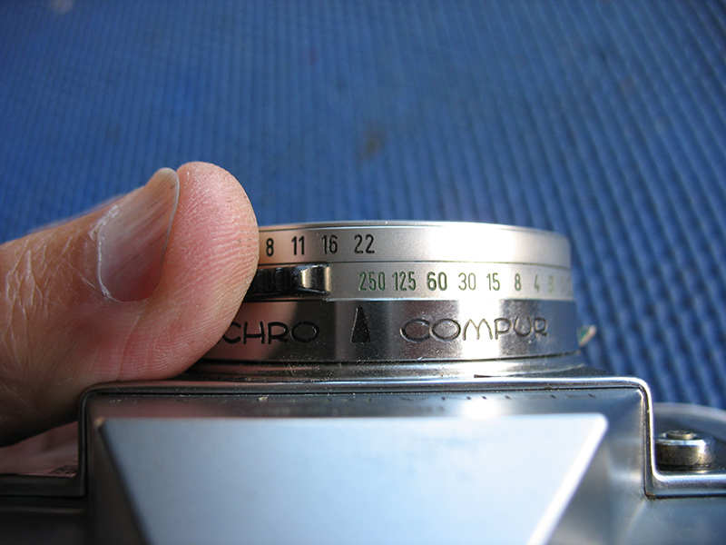
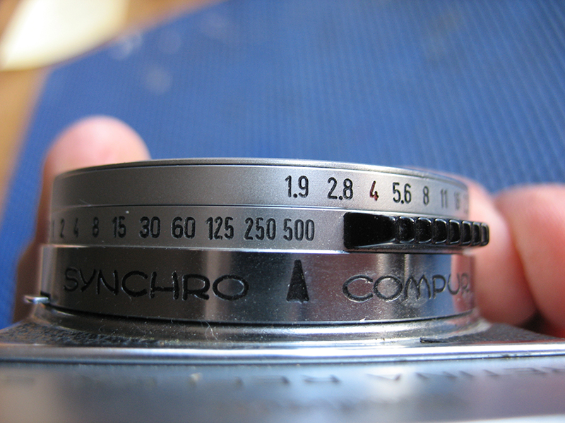
This completes the shutter reassembly to the camera body.
Next section: Final assembly.