Chris's camera pages
Retina Reflex S strip-down continued...cleaning and reassembling the shutter, part two.
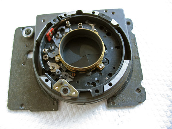
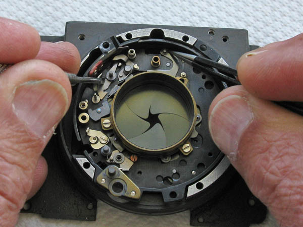
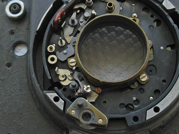
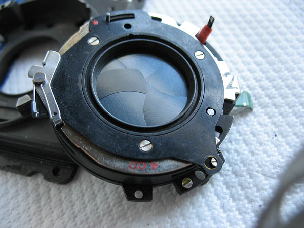
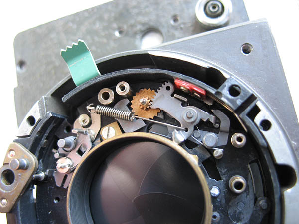
Here you can see that I'm using the stripped-out front plate from another Reflex S as a handy holder for the shutter to stop the flash contact at the back of the shutter getting unduly bent out of shape, but you can achieve much the same thing using a stray piece of board with a hole or two drilled in it instead.
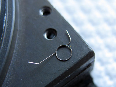
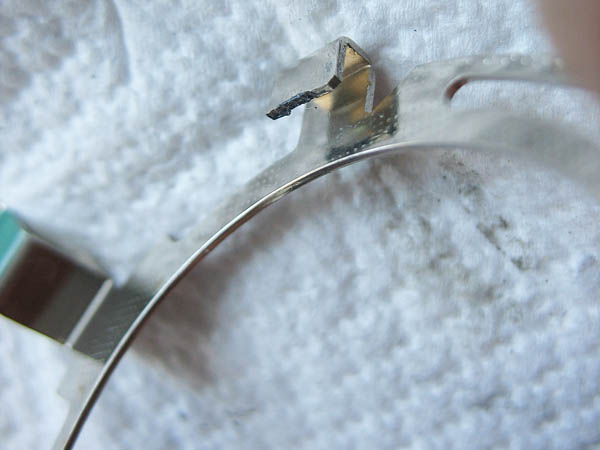
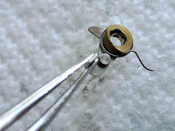
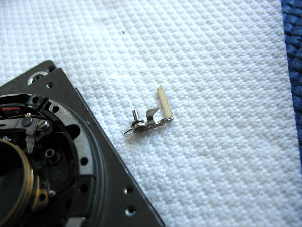
This is the spring from the synch locking lever.
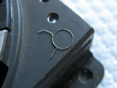
Note which way the spring is installed.The spring is extremely adept at disappearing into the distance never to be seen again, so take great care when hooking it over the stud on that lever. I usually hold a toothpick or screwdriver tip over the centre of the spring so it can't get away, and this can readily be achieved with only two hands.
Next install the 'B' lever spring. This sits in a groove on its post.
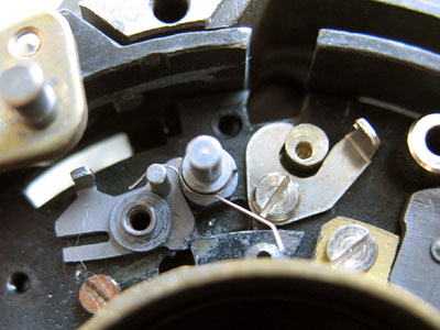
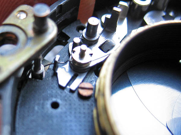
Hold back the catch and rotate the blade control ring to fully open the shutter blades.This will allow the B lever to drop into the slot on the blade actuating ring.
Place the B catch on the post. The B spring should fit into a small groove at the end of the lever.
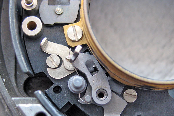
Place the spring and its screw in position. Check that the B lever can swing freely, and do the screw up tight.
Finally, rotate the spring like this.While holding the B lever back to disengage it from the blade control ring, pull the blade control ring back to the park position which will cause the blades to close.
Before fitting the flash set lever assembly and retaining plate, lubicate the spring in the case and the serated teeth on the lever assembly.
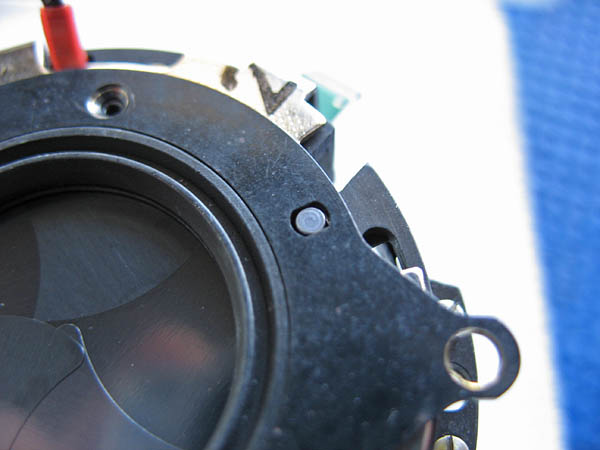
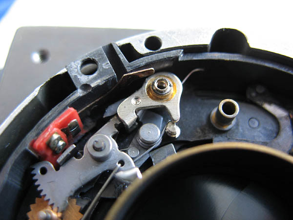
Fit the flash lever assembly by hooking in the tab on the assembly, then lowering it into position. The pin should be behind the spring like this.
Fit the retainer over the fixed post. The lever on the retainer should drop into the slot on the flash lever assembly like this.
Fit and tighten the three screws.
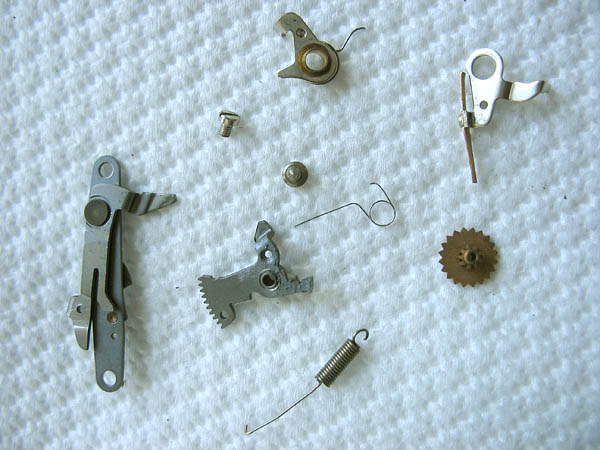
Next carefully clean the flash synch components.
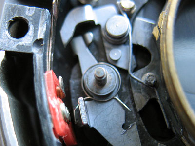
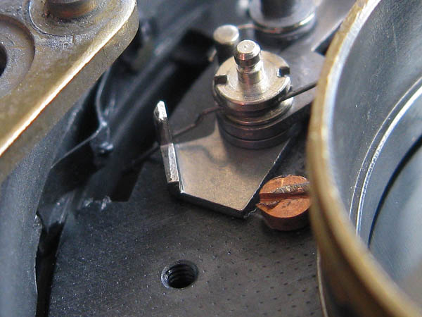
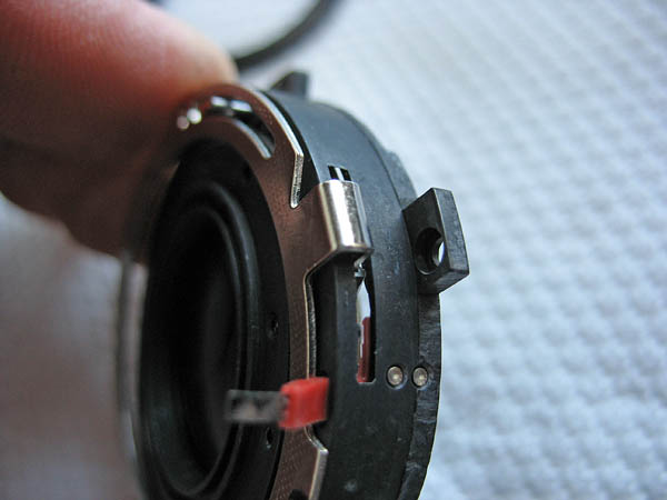
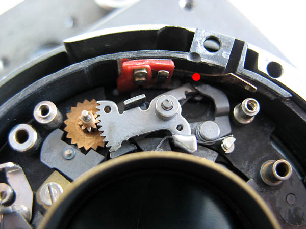
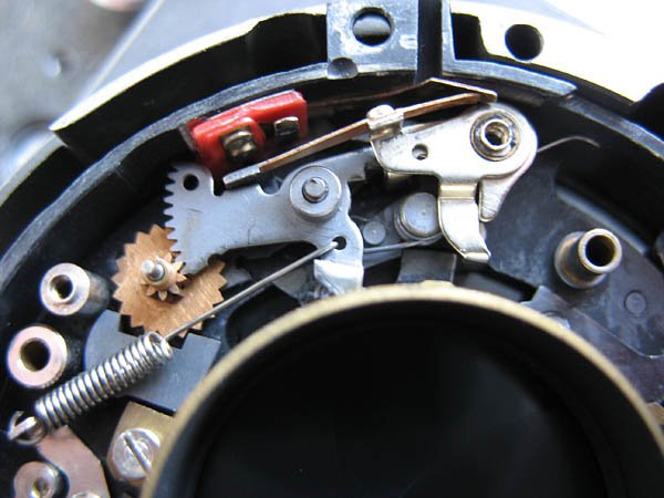
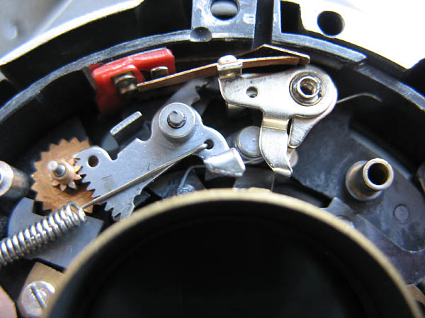
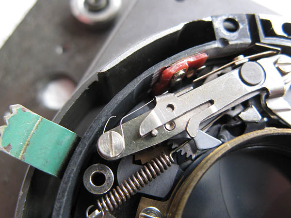
Place the gear assembly on the shaft, it should engage with the pallet. Place the synchro sector assembly on its post, this should engage witht he gear assembly.The tips of the synchro sector assembly and the lever with which it engages, marked here with a red dot, should be lubricated sparingly.
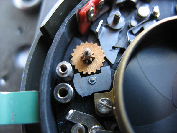
Fit the spring to the synchro sector assembly.
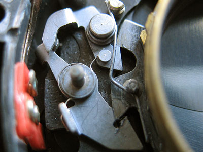
Apply some lubricant to the centre of the flash synch lever and fit over its post.
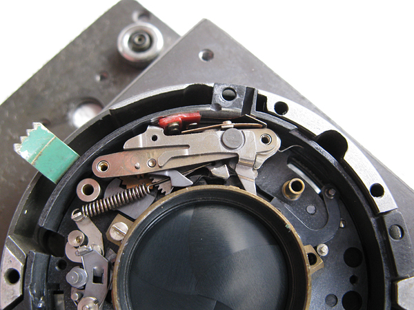
Fit the flash contact over the flash synch lever, and cock the flash synch mechanism by swinging the synchro sector assembly over until it latches in position.
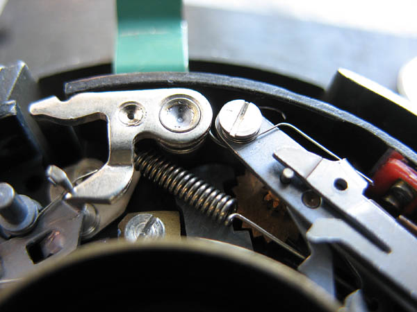
Place the cover plate in postion. Note the positions of the levers. Fit and tighten the fixing screw.
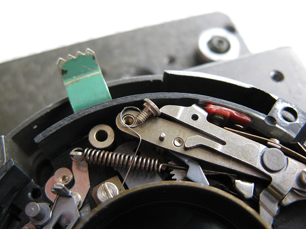
place the spring as shown. When tightening the screw be careful that the spring does not become trapped under the screw. Hook spring into the lever on the cover plate as shown.
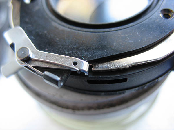
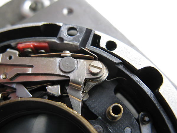
Next fit the trigger assembly. Apply lubricant to the post and to the tip of the trigger where it bears on the B lever. Fit the trigger in place, take care that the spring on the trigger sits as shown against the post on the flash synch mechanism. If it sits on the wrong side the release will not function correctly.
Next section: Cleaning and reassembling the shutter continued.