Chris's camera pages
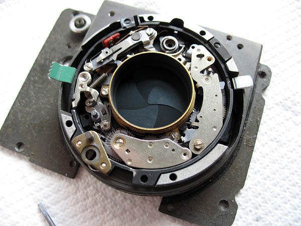
Retina Reflex S strip-down continued...cleaning and reassembling the shutter, part three.
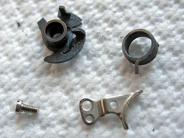
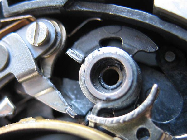
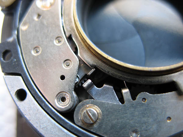
Clean the parts of the main drive assembly. Note that the screw that holds down the main drive stop is the same in appearance as those previously used in the other two positions on the tube assembly, but is slightly longer to allow for the thickness of the stop.The main drive should be lubricated inside and around the outside edge.
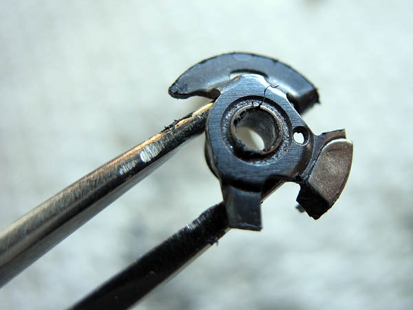
Fit the main drive in place, then place the stop in position. Be careful to make sure the stop is seated correctly over the stud on the mechanism plate.
Install and tighten the screw.Lubricate the inside of the main drive spring and place in position. The lower end of the spring fits into a hole in the main drive.
Hook the top end of the main drive spring into place on the stop.
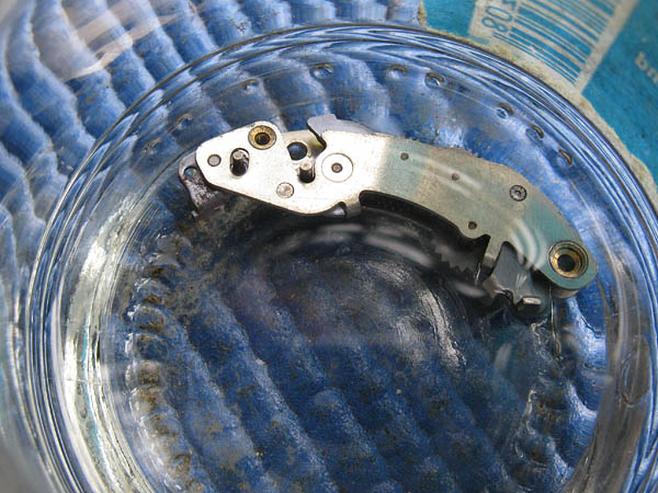
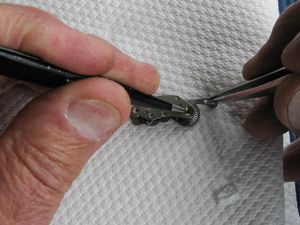
Next, cleaning, lubricating and installing the retard gear train and delay-action mechanisms.You can find a quick guide here for cleaning and checking the retard gear train here..."Retard gear train from a Retina IIIc Synchro-Compur shutter"Essentially, all that is usually required is to clean the retard gear train by working the mechanism while it is immersed in solvent. I usually work the action ten times as a default figure.Work the action by pushing the pin across with the tail of your tweezers.Blow any remaining solvent away and leave the retard gear train to dry.
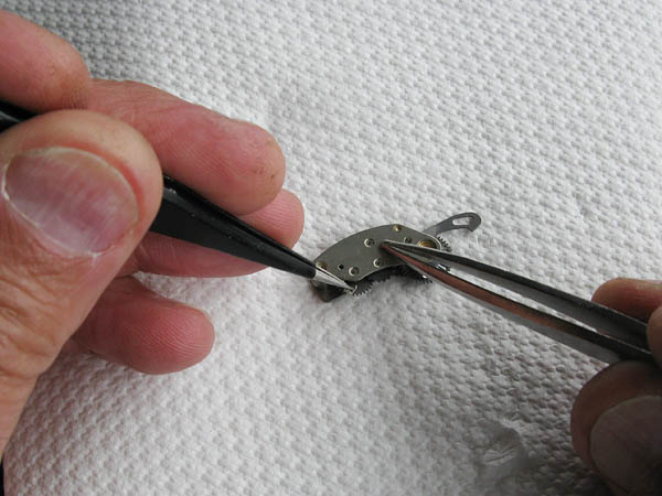
The delay-action is cleaned in much the same way. Simply set the delay-action by pulling the setting tab outwards, and run the mechanism by holding the release arm outwards. You don't need to pull this out very far, so take it easy or the return spring will be deformed.As with the retard gear train, do this with the mechanism immersed in solvent around ten times.Blow any remaining solvent from the delay action. Both the delay action and the retard gear train can be lubricated with graphite powder after they are quite dry. Puff a little graphite into the mechanisms and then work them a number of times to distribute it. Blow away any residual loose graphite.
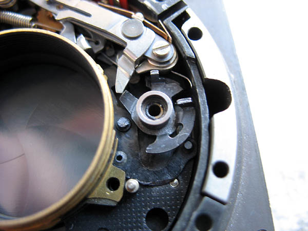
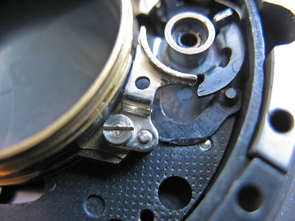
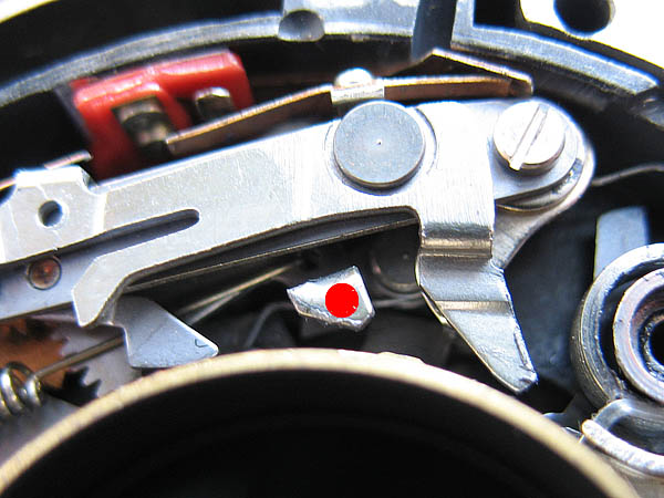
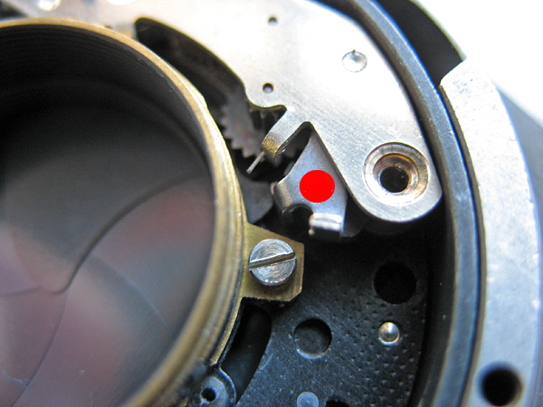
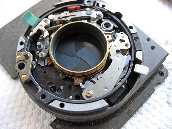
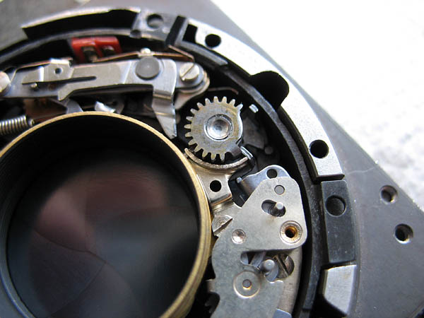
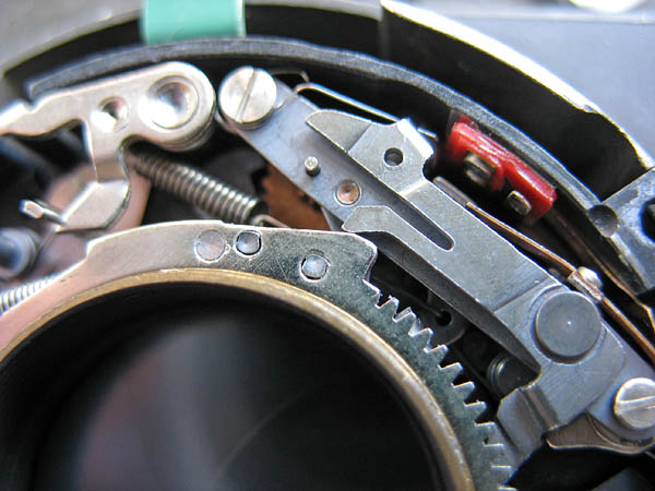
Multiple actions cock the shutter, start here by moving the tab on the synchro mechanism, marked with a red dot here, to the right until it latches. Then rotate the main drive assembly anti-clockwise until it is latched by the lever on the synch mechanism cover plate.
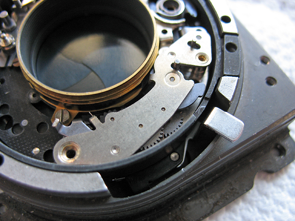
The retard gear train can now be installed. This is always installed with the shutter cocked.
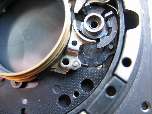
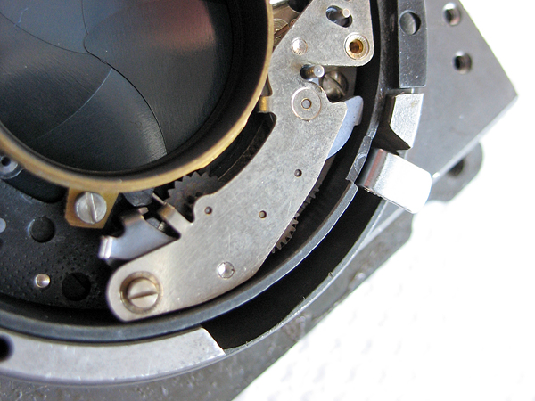
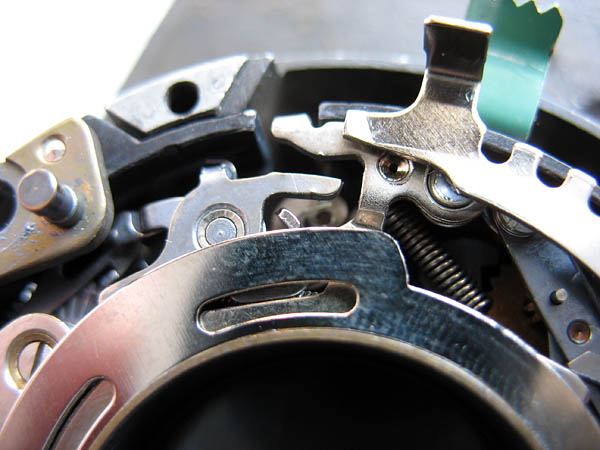
Settle the retard gear train into position. The lever, marked here with a red dot, should be pulled back so that it is in contact with the edge of the tab on the blade control ring, not sitting on top of it.
Install the long screw, but do not tighten it right up yet. Install the short screw. This is where the position of the retard gear train can be altered to adjust speeds. With the smaller screw loose you can swing this end of the retard gear train inwards towards the centre of the shutter to provide greater engagement with the main drive assembly, and so get longer exposure times, or outwards towards the outside of the shutter to get shorted exposure times. Set it about mid-way. Tighten both screws.
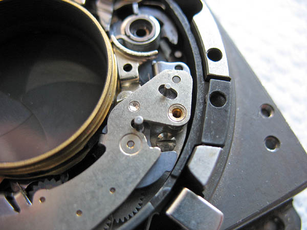
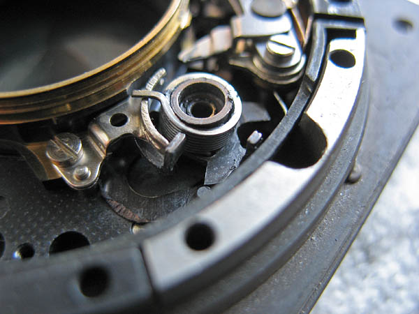
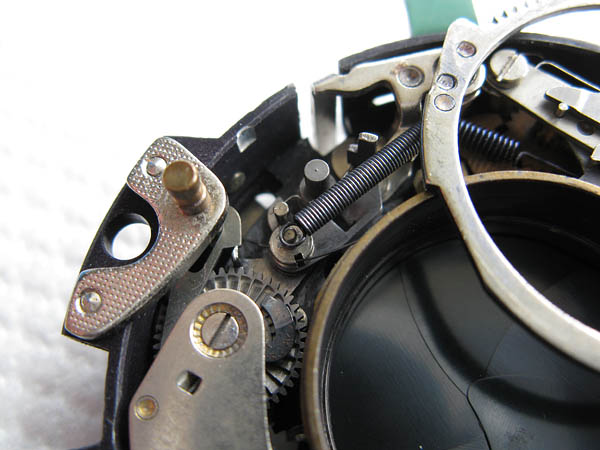
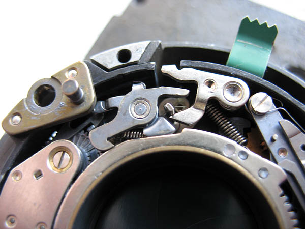
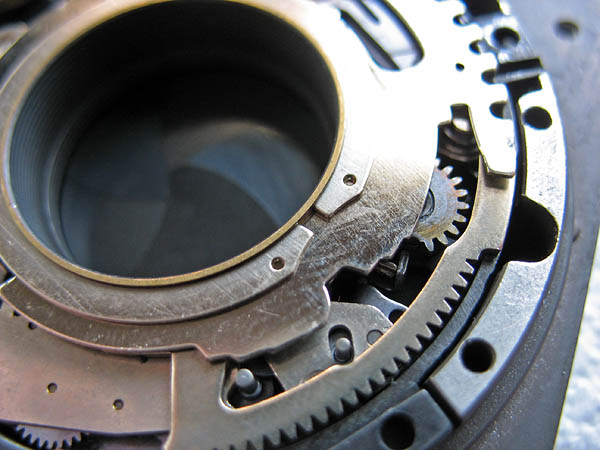
Fit the delay-action mechanism. It will probably help to pull out the setting tab to allow you to fit it in place. Check that it sits much as in the picture.
Once the delay-action mechanism is settled correctly into position it should be at or just below the edge of the case. Tighten the single screw.Lubricate the shaft on the gear assembly and place into position over the main drive. Take note of where the tab sits against the main drive.
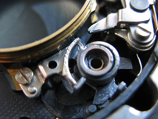
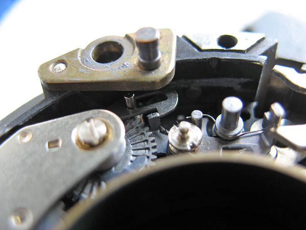
Before fitting the cocking ring I lubricate it lightly around the inside edge and around the outside where it acts on various parts of the mechanism. Hook the spring on the cocking ring over the post and place the cocking ring into position.Note the timing of the teeth on the cocking ring and gear assembly.
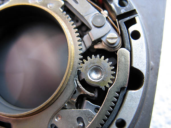
The cocking ring contacts the tab on the delay-action mechanism, just above this you see a notch. This is where the lock assembly engages.Both of these points should be lightly lubricated.In the second photo you can see where the cam section of the cocking ring contacts the lever on the synch mechanism cover plate. This should also be lightly lubricated.
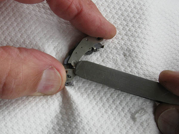
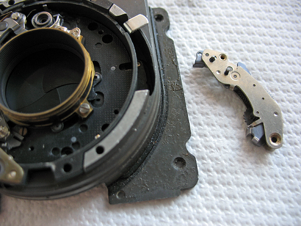
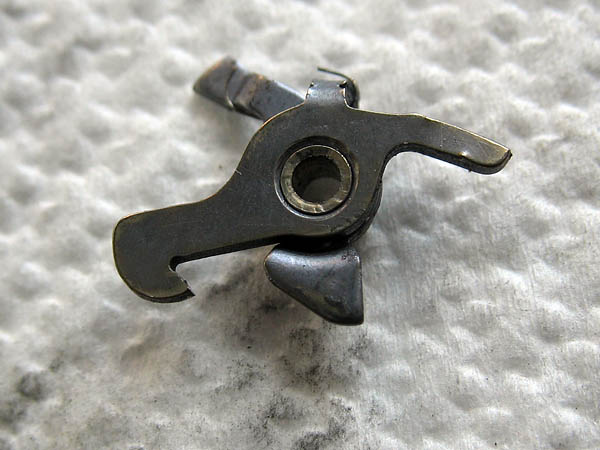
The lock assembly, shown below, consists of two levers joined with a single rivet forming a pivot and a spring. The levers should be free to move relative to each other on that pivot otherwise the shutter will fail to cock correctly.Fit the lock assembly into position.
As with the cocking ring, the speed ring should be lubricated lightly on the inside edge and on the outside edge where it contacts the pin on the retard gear train and the tip of the B lever. Fit the speed ring in place then fit the retainer, which sits in a groove on the tube assembly.
The shutter is now complete and only requires testing before being fitted into the lens mount assembly.
Next section: Cleaning and reassembling the shutter continued.